
What Is Aluminium Window Sill Flashing and Why It Matters
Every window opening in an exterior wall is a hole in your building’s weather defence. Rain hits the glass, runs down the frame, and collects at the lowest point — the sill. Without a reliable way to intercept and redirect that water, it migrates into the wall cavity and quietly rots framing timber for years before anyone notices.
What Aluminium Window Sill Flashing Actually Is
Aluminium window sill flashing is a pre-formed or site-bent aluminium profile installed beneath the window frame at the sill to intercept moisture and redirect it away from the wall cavity. It functions as a sloped tray — complete with upturned edges at the back and sides — that catches any water passing the window unit and channels it outward to the building exterior. Unlike general window flashing, which refers to the full system of tapes, membranes, and metal pieces surrounding all four sides of an opening, sill flashing addresses only the base — the single point where water accumulates most aggressively.
So what does window flashing look like across a complete installation? It includes jamb membranes on the vertical sides, head flashing at the top acting as a drip cap, and the sill pan at the bottom. Each layer overlaps the one below in shingle fashion. The aluminium sill component sits at the foundation of this layered system, making it the first and most critical piece installed during flashing for windows.
Why the Window Sill Is the Most Vulnerable Point
Three forces conspire against the window sill. Gravity pulls water downward to the lowest edge of the frame. Capillary action draws moisture into tight gaps between the frame and rough opening. Wind-driven rain pushes water horizontally into joints that would otherwise stay dry. All three concentrate their effect at the sill — not the head, not the jambs.
Head flashing and jamb membranes manage water that passes by. Sill flashing manages water that stops and pools. That distinction is why a missing sill pan causes more concealed damage than any other single flashing failure in residential construction.
Research from Building Science Corporation identifies four essential characteristics a sill pan must deliver: a continuous waterproof surface, a back dam or positive slope directing water outward, end dams preventing lateral migration, and proper lapping over the drainage plane below. When any one of these fails, water finds the path of least resistance — straight into your wall framing.
The question isn’t whether your window sill flashing will encounter moisture. It’s whether the profile, slope, and integration are good enough to handle the volume your climate delivers — and that depends on materials, geometry, and how the sill pan works within a broader layered defence system.
How Aluminium Sill Flashing Works as a Layered Defence System
A single material can’t guarantee watertightness forever. Sealants age, metals expand, and wind-driven rain finds gaps that didn’t exist when the building was new. That’s why modern exterior window flashing relies on redundancy — multiple layers working together so that if one element fails, the next catches what slips through.
Aluminium sill flashing sits at the heart of this layered strategy, but it doesn’t work alone. Understanding how it interacts with secondary membranes and substrate protection is the difference between a wall that stays dry for decades and one that develops concealed rot within five years.
Primary Flashing vs Secondary Waterproof Membranes
Think of the system in two tiers. The primary layer — your aluminium sill pan — handles bulk water. This is the high-volume runoff that streams down the window face during a storm and pools at the sill. Rigid aluminium manages this load well because it holds its shape under water pressure, resists UV degradation, and won’t compress or deform over time the way some flexible products can.
The secondary layer sits beneath the aluminium pan, directly on the rough opening substrate. It’s typically a self-adhering membrane or waterproof flashing tape for windows that seals the timber or steel framing below. Its job is fundamentally different: it doesn’t redirect bulk water outward. Instead, it acts as a last-resort barrier for any moisture that bypasses the primary flashing — whether through a degraded sealant joint, a fastener penetration, or capillary movement around the pan’s edges.
This two-tier approach mirrors how professional building envelope consultants think about flashing windows and doors across an entire structure. No single product carries the full responsibility. The aluminium component deflects; the membrane protects. Together, they create tolerance for the imperfections that every real-world installation contains.
How the Layered Defence System Prevents Failures
Not every project demands a full secondary membrane beneath the sill pan. Single-storey homes in sheltered locations with wide eaves may perform adequately with a well-installed aluminium pan alone. But certain conditions raise the stakes considerably and make that backup layer essential:
Multi-storey buildings where windows sit high on exposed walls catch significantly more wind-driven rain. Coastal properties face salt-laden moisture driven horizontally into joints. Homes without protective eaves expose their window openings to direct rainfall. In these scenarios, the secondary membrane transforms from a nice-to-have into a requirement.
When properly assembled, the complete sill flashing system stacks in a specific sequence from exterior to interior:
- Drip edge or front lip — the outermost projection of the aluminium pan that throws water clear of the cladding below
- Primary aluminium sill flashing — the rigid pan that intercepts and redirects bulk water outward
- Self-adhering membrane — waterproof flashing tape or sheet membrane sealed to the rough opening sill and jambs
- Substrate protection — the structural sill framing (timber or steel), kept dry by everything above it
Each layer overlaps the one below in shingle fashion, following the fundamental principle that water runs downhill. The membrane wraps up the back and sides of the rough opening, lapping under the weather-resistive barrier (or building wrap) above and over it below. The aluminium pan then sits on top of this prepared surface, with its back dam tucked beneath the jamb membranes that follow.
Australia’s National Construction Code (NCC) requires that flashing in windows and external door openings prevents water from entering the building fabric. The code doesn’t prescribe a single method but mandates that the installed system perform to this standard — giving builders flexibility to choose materials while holding them accountable for results. International standards reinforce the same principle: the IRC Section R703.4 requires that pan flashing be sealed or sloped to direct water outward, and that openings using pan flashing also incorporate protection at the head and sides.
The practical takeaway? Sill flashing for windows isn’t just a single aluminium profile screwed into place. It’s an assembly. The aluminium pan does the heavy lifting, but the membrane beneath ensures that even when conditions overwhelm the primary layer — a blocked drip edge, a cracked sealant line, a once-in-a-decade storm — your wall framing stays dry. Getting the layer sequence right matters as much as the materials themselves, which raises an obvious next question: how do you choose between the available flashing materials for each layer of this system?
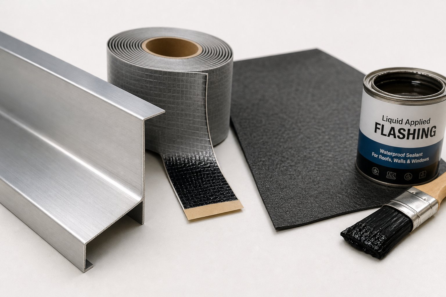
Comparing Flashing Materials for Window Sill Applications
Four material categories dominate the market for sill flashing: rigid metal, flexible tape, self-adhering membrane, and liquid-applied products. Each has a legitimate role within a complete window assembly, but they aren’t interchangeable — particularly at the sill, where ponding water, UV exposure, and mechanical load separate materials that endure from those that eventually fail.
Aluminium Rigid Flashing for Sill Applications
Metal window sill flashing made from aluminium is the strongest performer for primary sill pan duty. The reasons are practical rather than theoretical. Aluminium holds precise bends permanently — once you form an end dam or back dam, it stays in shape for the life of the building. It doesn’t creep, sag, or lose its profile under the sustained weight of a window frame sitting on top of it.
UV degradation is a non-issue. Unlike adhesive-based products that can break down when exposed to sunlight during construction delays, aluminium tolerates weeks or months of UV exposure without losing performance. It’s also compatible with virtually every cladding system used in Australian residential and commercial construction — brick veneer, rendered walls, fibre cement, and timber weatherboard all integrate cleanly with metal sill flashing profiles.
Longevity is where aluminium separates itself most decisively. A properly installed window aluminum flashing pan will outlast the window it protects, the sealants around it, and often the cladding system itself. For coastal locations along Australia’s eastern and western seaboards, marine-grade aluminium (typically 5000-series alloys) resists the corrosive effects of salt-laden air that would compromise lesser metals within a decade.
Flexible Tape and Self-Adhering Membrane Options
Flexible flashing tape and self-adhering membranes serve different purposes depending on the project. In many installations, they function as the secondary waterproof layer beneath a rigid aluminium pan — and they’re excellent in that role. Their conformability lets them wrap into corners, seal over fastener penetrations, and bridge irregular substrates that a rigid material can’t follow.
Can they serve as primary sill flashing? In limited circumstances, yes. Low-exposure single-storey openings beneath deep eaves, where water volumes stay minimal and UV exposure is negligible, may perform adequately with a quality self-adhering membrane alone. But the moment you introduce sustained water contact, foot traffic during construction, or direct sun exposure, flexible products hit their limits. Adhesive-backed products are convenient to install but aren’t engineered for the long-term mechanical demands a sill pan faces — compression under frame weight, thermal cycling, and constant moisture contact.
Liquid-applied flashing fills a useful niche for irregular geometries and retrofit situations where a pre-formed metal pan can’t fit. Applied as a thick coating, it cures into a seamless waterproof layer that handles complex corners without laps or joints. The trade-off is slower installation (cure times vary with temperature), lower mechanical durability than metal, and difficulty inspecting it once the window is installed.
Choosing Materials Based on Exposure and Climate
Climate drives material selection more than budget or convenience. Coastal properties from the Sunshine Coast down to the Mornington Peninsula deal with persistent salt air that corrodes standard metals and degrades adhesives prematurely. Marine-grade aluminium thrives in these conditions. Tropical regions across northern Queensland and the Northern Territory introduce extreme heat and humidity — adhesive-based products can soften, lose bond strength, or telegraph through finishes when substrate temperatures climb above 60°C on sun-facing walls.
Cold climates in alpine regions of Victoria and NSW demand materials that remain flexible at low temperatures (favouring membranes for secondary layers) while staying rigid enough to shed snow melt (favouring metal for primary pans). The table below summarises how each material type performs across the criteria that matter most for sill applications:
| Material | Durability | Sill Suitability | Ease of Installation | Cost | Best Use Case |
|---|---|---|---|---|---|
| Aluminium rigid flashing | Excellent — 50+ year lifespan, UV-stable, corrosion-resistant in marine grades | Highest — holds bends, supports frame weight, manages bulk water | Moderate — requires precise measurement and brake forming | $$ — mid-range supply, higher if custom-fabricated | Primary sill pan for all exposure levels, especially coastal and multi-storey |
| Flexible flashing tape | Moderate — 15-25 years depending on UV exposure and adhesive quality | Limited as primary — suitable for low-exposure sills or as secondary layer | Easy — peel-and-stick application, no special tools | $ — lowest material cost | Secondary membrane beneath metal pan; primary only on sheltered, single-storey openings |
| Self-adhering membrane | Good — 20-30 years when protected from UV and not under mechanical load | Moderate — works well as secondary layer, less reliable as standalone sill pan | Easy to moderate — requires clean, primed substrates for proper bond | $$ — mid-range | Secondary waterproof layer on rough opening substrate; backup defence beneath aluminium pan |
| Liquid-applied flashing | Good — 20-30 years, seamless so no lap failures | Moderate — no mechanical rigidity, can’t support frame weight or hold slope independently | Moderate to difficult — requires correct film thickness, temperature-sensitive cure | $$$ — highest material and labour cost | Complex geometries, retrofit situations, and transitions where rigid metal can’t conform |
The pattern is clear: metal window flashing made from aluminium delivers the strongest combination of durability and sill-specific performance. Other materials play supporting roles — important ones — but they work best when backing up a rigid primary pan rather than replacing it. For most Australian homes and commercial builds, the optimal approach pairs an aluminium sill pan with a self-adhering membrane beneath it, selecting the membrane grade based on climate exposure.
Choosing the right materials, however, only solves half the problem. Even premium aluminium fails when critical geometry details — end dams, back dams, and corner joints — are undersized, missing, or poorly sealed.
End Dams, Back Dams, and Corner Joints That Prevent Failures
A perfectly sized aluminium flashing pan means nothing if water escapes around its edges. The flat drainage surface gets most of the attention during installation, but the real engineering happens at the perimeter — the upturned edges and sealed corners that contain water and force it toward the building exterior. These details are where pan flashing for windows either performs or quietly fails.
End Dams and Why They Prevent Lateral Water Migration
End dams are the upturned edges at each side of the sill pan. Picture a shallow baking tray — without raised sides, liquid runs straight off the edges. The same physics applies at the subsill window area. Water pooling on the flashing pan travels laterally toward the lowest point, and without end dams, that path leads directly off the sides and into the wall cavity at the jamb corners.
Missing or undersized end dams are the single most common sill flashing failure in residential construction. Building Science Corporation identifies end dams as one of four essential characteristics every pan flashing must deliver, specifically because lateral water migration into the wall is nearly impossible to detect until rot is well advanced. The damage occurs behind finishes, out of sight, and by the time staining appears on interior linings the framing has often been compromised for years.
Height matters. End dams that barely rise above the pan surface get overtopped during heavy rain events when water volume exceeds what the slope can drain fast enough. A minimum height of 25 mm is standard practice for most residential applications, with 40 mm or more recommended on multi-storey walls, exposed elevations, or climate zones with intense wind-driven rain.
Back Dams and Their Role in Directing Water Outward
While end dams prevent sideways escape, the back dam stops water from migrating inward toward the wall sheathing. It’s the rear upturn of the flashing pan — the edge closest to the building interior — and it forces every drop of water on the pan surface to travel in one direction only: outward toward the drip edge.
Without a back dam, water that pools on the sill during a storm can creep backward by capillary action, especially where the window frame compresses against the pan surface and creates a thin film pathway. Wind pressure during storms amplifies this effect, actively pushing water toward the interior of the wall assembly.
For site-bent aluminium profiles, the back dam is formed by bending the rear edge of the pan upward at a 90-degree angle. A strip of timber nailed across the back of the rough opening sill can also serve as a back dam substrate beneath a membrane layer, creating positive slope toward the exterior while blocking rearward migration. As Building Science Corporation notes, the back dam of a manufactured pan must be protected against bending and breakage during window installation — a heavy window frame set carelessly can flatten a back dam and eliminate its function entirely.
Corner Lap Joints and Proper Sealing Techniques
The corners where end dams meet back dams are the highest-risk points in any flashing pan assembly. Two vertical surfaces intersect at a 90-degree angle, creating a joint that must remain watertight under sustained hydrostatic pressure from pooled water. If this corner leaks, water enters the wall at the worst possible location — the base of the jamb, where it can wick upward through timber framing and spread damage far beyond the visible sill area.
When flashing around windows with aluminium, the preferred technique for corner treatment is a folded “dog ear” rather than a cut-and-sealed joint. A dog ear folds the excess material at the intersection into a flat lap, maintaining continuous metal across the corner without relying on sealant alone. Building Science Corporation recommends folding rather than cutting at these inside corners precisely because a butt joint sealed with caulk will eventually crack as the sealant ages and the building moves through thermal cycles.
For membrane-based pans, flashing window corners demands that the material be pressed tightly into the 90-degree junction without spanning or “chamfering” across the corner. A membrane that bridges the corner rather than sitting tight against it creates a void — and when the window frame slides into place, the frame’s corner can puncture that unsupported span, opening a hole at the exact point where water concentrates most.
The most common failure modes at sill flashing corners and edges include:
- Inadequate end dam height — dams too short to contain water volume during heavy rain, allowing overtopping at the jamb corners
- Missing back dam — no rear upturn to block inward water migration, leaving framing exposed to capillary and wind-driven moisture
- Unsealed corner joints — cut corners without folding or proper sealant application, creating a direct water path into the wall cavity
- Improper lap direction — jamb flashing tucked behind end dams rather than overlapping them, reversing the shingle principle at the most critical junction
- Insufficient slope — a level or back-sloped pan that allows water to pond against the back dam rather than draining outward to the drip edge
Each of these failures is preventable with correct geometry and careful execution. The frustrating reality is that most sill leaks trace back to one of these five issues rather than to material defects or unusual weather events. Getting the dams right and sealing the corners properly accounts for the majority of long-term flashing performance — which raises the next practical question: what measurements, angles, and slope specifications actually define “right” for these critical dimensions?

Measurements, Angles, and Slope Specifications for Proper Drainage
Knowing where end dams and back dams go is one thing. Knowing how tall to make them, how far the front lip should project, and how much slope the pan needs to actually drain — that’s where flashing a window sill moves from theory into buildable reality. These numbers aren’t arbitrary. They’re driven by water volume, frame depth, and the physics of drainage under real storm conditions.
Slope and Drainage Angle Requirements
A flat sill pan doesn’t drain — it ponds. And ponded water eventually finds a way through any joint, no matter how well sealed. Every aluminium sill pan must maintain a positive outward slope so gravity moves water toward the drip edge rather than letting it sit against the back dam and creep inward.
How much slope is enough? Industry guidance from building envelope specialists recommends a minimum pitch of approximately 6 degrees (roughly equivalent to a 12 mm fall over a 100 mm depth). For deeper sill pans — those exceeding 150 mm in depth — a steeper pitch becomes more important because water travels a longer path to reach the exterior edge.
Achieving slope happens through one of three methods:
- Shimming the substrate — a tapered piece of bevelled timber (such as weatherboard offcut) nailed to the rough opening sill creates a sloped surface beneath the pan
- Pre-bent aluminium profiles — the pan itself is brake-formed with the slope built into the bottom surface, eliminating the need for substrate modification
- Sloped framing — during new construction, the sill member of the rough opening can be cut or planed at the required angle before the pan is installed
The sloped framing approach is simplest in new builds. Retrofit situations typically rely on shimming or pre-bent pans because the existing rough opening can’t be easily modified with a window already removed and weather exposure a concern.
Bend Specifications and Standard Dimensions
Getting the metal flashing for window sill applications right means measuring four critical dimensions before picking up the brake. Each measurement feeds into the next, so the sequence matters:
- Measure rough opening width plus end dam extensions — the pan must span the full opening width, with additional material at each side (typically 25-40 mm per side) that folds up to form the end dams
- Determine back dam height based on frame depth — the rear upturn should reach at least 50 mm up the back of the rough opening, high enough to sit behind the window frame’s rear flange and prevent any back-flow during wind-driven events
- Calculate front projection for adequate drip clearance — the front lip needs to extend far enough beyond the face of the cladding below (minimum 10-15 mm past the wall plane) to throw water clear rather than allowing it to track back under the pan via surface tension
- Set end dam height based on expected water volume — 25 mm minimum for sheltered single-storey openings; 40 mm or more for exposed, multi-storey, or high-rainfall locations where the pan may hold water temporarily during peak flow
Total pan width — measured from the front drip edge to the top of the back dam when laid flat before bending — typically runs between 200 mm and 300 mm for standard residential window frames. Wider commercial frames or deep reveals may need 350 mm or more. The aluminium stock gauge for residential applications is usually 0.55 mm to 0.8 mm — thick enough to hold bends permanently without being so heavy that it resists forming in a hand brake.
Mock-Ups and Water Testing for Critical Installations
For multi-storey projects, high-exposure elevations, or any situation where a new window product or installation detail is being used for the first time, building a full-scale mock-up and running a water test before committing to production is standard practice among professional building envelope consultants.
The concept is straightforward: build one complete window opening — framing, membrane, aluminum sill pan, window unit, and all flashing at window perimeter — then hit it with water and watch what happens. Modular construction firms routinely conduct these tests with spray nozzles positioned approximately 450 mm away from the assembly, simulating rainfall while using differential pressure to replicate wind-driven conditions. A third-party proctor typically oversees the process to ensure it meets industry testing standards.
For contractors and advanced DIYers tackling a single residential installation, a simplified version still provides valuable confidence. After installing the flashing window sill assembly and before fitting the window unit, run a garden hose at low pressure across the sill pan for ten to fifteen minutes. Check for any water appearing behind the back dam, leaking at the corner joints, or pooling rather than draining. If water ponds anywhere or escapes at the corners, the slope or dam geometry needs correction — and it’s far easier to fix before the window goes in than after.
This test-before-you-commit approach catches the measurement and fabrication errors that cause long-term failures. A pan that drains perfectly under hose testing will handle decades of real storms. One that ponds or leaks during a controlled test will only perform worse under actual wind-driven rain with a window frame compressing the assembly.
Of course, these dimensions and angles don’t exist in isolation. The flashing pan must integrate with whatever’s on the wall around it — and the details shift significantly depending on whether that wall is brick veneer, rendered masonry, fibre cement, or timber weatherboard.
Integrating Sill Flashing With Different Wall Cladding Systems
A perfectly formed aluminium sill pan with correct slope, generous end dams, and sealed corners still fails if it doesn’t integrate properly with the wall system around it. Brick veneer demands a different projection distance than timber weatherboard. Stucco requires termination details that fibre cement doesn’t. The cladding material dictates how the sill flashing connects to the drainage plane, where it laps, and how far it must project to throw water clear of the wall below.
Most installation guides treat sill flashing as a standalone component. In reality, the same aluminium pan needs different dimensional allowances and lapping sequences depending on what’s wrapping the rest of the building.
Brick Veneer Sill Flashing Details
Brick veneer is Australia’s most common wall system for residential construction, and it introduces unique challenges at the window sill. The brick sill course sits proud of the framing plane, which means the aluminium sill pan must project far enough outward to clear the masonry below while directing water into the drainage cavity rather than onto the brick face.
The critical detail is weep hole alignment. Water leaving the sill pan’s drip edge needs a clear path into the cavity behind the brick, where it can drain down to the through-wall flashing at the base of the wall and exit via weep holes in the lowest course. If the brick window sill course blocks this path — or if mortar droppings have clogged the cavity — the sill flashing redirects water but gives it nowhere to go. The International Masonry Institute’s window sill detail for veneer walls illustrates how sill flashing with end dams must integrate with the drainage mat behind the brick to ensure moisture diverts outward through weep vents rather than pooling against the sheathing.
For brick sill detail work, the aluminium pan typically needs 50-75 mm of front projection beyond the face of the framing to bridge across the cavity space and direct water past the inner leaf. End dams must be tall enough — generally 40 mm minimum — to account for the additional water volume a window brick sill collects from rain running down brickwork above the opening. The mortar bed beneath a rowlock brick sill should slope outward and not compress or block the top edge of the aluminium flashing where it transitions from the rough opening to the exterior.
Stucco and Fibre Cement Wall Integration
Rendered and fibre cement walls present a different problem. Both claddings sit relatively close to the framing plane, so the sill pan doesn’t need as much outward projection as brick veneer — typically 10-20 mm past the finished cladding face is sufficient. But the termination detail at the junction between flashing and cladding becomes critical.
When flashing a window for stucco, the sill pan must terminate at a weep screed or stucco stop that creates a clean break between the render and the flashing surface. Building research from the Pacific Northwest National Laboratory confirms that stucco will always crack and that water management behind the render depends entirely on proper flashing integration and drainage plane continuity. A sealant joint between the aluminium drip edge and the stucco stop below must remain flexible enough to accommodate thermal movement without cracking — silicone or polyurethane sealants perform better here than rigid acrylic products.
Fibre cement panelling handles the transition differently. The panel edge typically butts against the underside of the sill pan’s drip edge, with a 6-10 mm gap left open for drainage. Caulking this gap shut — a common mistake — traps moisture behind the cladding and defeats the purpose of the flashing system entirely. The same principle applies as with lap siding: leave that gap open so water that collects behind the cladding can weep out freely.
Wood Siding and General Lap Cladding
Timber weatherboard and other lap claddings follow the simplest integration logic, but the lapping sequence is unforgiving. The aluminium sill pan must sit beneath the weather-resistive barrier (building wrap) at the back and sides while its front drip edge extends over the top of the cladding course immediately below the window. This shingle-style overlap ensures water flowing down the drainage plane behind the wrap reaches the sill pan and exits at the front, while water on the face of the cladding continues downward without being directed behind the boards.
LP Building Solutions’ technical guidance emphasises that flashing must slope away from the wall — never toward it — and that a minimum 10 mm gap between the sill pan’s drip edge and the top of the board below allows moisture to escape rather than being trapped by the cladding pressing tight against the flashing.
For lap cladding, the membrane overlap is straightforward: the building wrap laps over the back dam and sides of the pan, with the upper courses of wrap then covering the jamb flashings above. End dam height can be slightly lower than brick veneer applications — 25 mm is typically adequate for single-storey weatherboard homes with reasonable eave protection — because the wall cavity doesn’t hold the same volume of water as a masonry drainage cavity.
| Wall System | End Dam Requirement | Front Projection Distance | Membrane Overlap | Special Considerations |
|---|---|---|---|---|
| Brick veneer | 40 mm minimum — higher on exposed, multi-storey elevations | 50-75 mm past framing to bridge cavity | Membrane wraps up back and sides; laps under building wrap above | Align with weep holes; avoid mortar blockage of drainage cavity; brick sills window course must slope outward |
| Stucco / render | 30-40 mm — accounts for render thickness at jambs | 10-20 mm past finished render face | Two-layer WRB behind render overlaps pan; membrane laps onto stucco stop | Flexible sealant at stucco stop junction; weep screed below must remain unblocked |
| Fibre cement | 25-35 mm — moderate exposure typical | 10-15 mm past panel face | Building wrap over back dam; panel butts beneath drip edge with gap | Do not caulk gap between drip edge and panel below; allow free drainage |
| Timber weatherboard | 25 mm minimum — adequate for sheltered single-storey | 10-15 mm past face of board below | Wrap laps over back dam and sides; drip edge overlaps top of cladding board | Maintain 10 mm gap between drip edge and board; ensure wrap is not punctured by pan fasteners |
New Construction vs Retrofit: How the Approach Changes
New construction offers complete access to the rough opening, meaning the full lapping sequence — membrane first, then pan, then window, then jamb and head flashings — can proceed in correct order. The aluminium sill pan integrates cleanly with whichever cladding system follows because nothing is in the way yet.
Retrofit projects complicate matters considerably. The existing cladding is already in place, so the sill pan must slide beneath the window frame and integrate with materials that can’t be easily removed or repositioned. In brick veneer retrofits, the brick window sill details often prevent the ideal projection distance because the mason’s work is fixed. Cutting into rendered walls to properly lap new flashing behind existing stucco is invasive and expensive. Weatherboard retrofits are somewhat more forgiving — individual boards can be temporarily removed to access the flashing plane beneath.
The practical solution for many retrofit scenarios is a combination approach: install the best possible aluminium sill pan within the accessible space, then supplement with liquid-applied or self-adhering membrane products at transitions where rigid metal can’t achieve proper laps. It’s a compromise, but a well-executed hybrid beats an absent or poorly integrated pan every time.
With the cladding interface resolved, the focus shifts to execution — specifically, the installation sequence and common mistakes that undermine even well-designed flashing details.

Installation Failures and How to Prevent Them
Correct materials and perfect geometry still produce leaking windows when the installation sequence goes wrong. Most sill flashing failures trace back to a handful of preventable mistakes — errors that experienced builders and DIYers alike repeat because the consequences stay hidden inside walls for years before becoming obvious. Understanding what goes wrong, and why, makes the correct approach intuitive rather than just another checklist to memorise.
Common Installation Mistakes That Cause Water Damage
The single most destructive error when flashing a window is reverse lapping. This happens when a flashing layer gets tucked behind the material below it instead of overlapping it. Water running down the wall hits that exposed upper edge and flows directly behind the flashing — the exact path it was supposed to block. As VERTEX Engineering notes, if you can see the uppermost edge of a flashing piece or weather-resistive barrier from the exterior, it’s likely a reverse lap condition. The fix is simple in principle but demands discipline: every layer must shingle over the one below, from head to sill, no exceptions.
Other failure modes are equally common and just as damaging:
- Inadequate slope creating ponding — a level or back-sloped sill pan holds water against the back dam and sealant joints rather than draining it outward. Even 2 mm of standing water sustained over months degrades sealant and finds micro-cracks that a draining pan would never expose to hydrostatic pressure.
- Incompatible sealants that degrade aluminium — certain acetic-acid-cure silicones and alkaline sealants corrode aluminium over time, pitting the surface and creating pinhole leaks along sealed joints. Always verify sealant compatibility with aluminium before application — neutral-cure silicone and polyurethane sealants are safe choices.
- Fastener penetrations through the pan area — screws or nails driven through the flat drainage surface of the sill pan create direct water entry points. Every penetration is a potential leak, especially when the fastener loosens over thermal cycles. Fasteners belong in the back dam or the vertical face of end dams — never in the flat pan surface where water sits.
- Applying flashing over building wrap at the sill — industry professionals identify this as one of the top installation errors. Flashing tape or membrane adhered over house wrap at the rough opening sill doesn’t seal to the structural substrate, leaving water a clear path behind both layers at the corners.
Each of these mistakes shares a common trait: they’re invisible once the window frame and flashing window trim are in place. The cladding goes on, the job looks complete, and the failure mode stays dormant until a severe enough rain event exposes it — often years later when repair costs have multiplied.
Proper Installation Sequence for Lasting Performance
The correct sequence when flashing over window rough openings follows one core principle: work from the bottom up, and from the inside out, so every layer drains onto the one below. Here’s the step-by-step order for metal flashing around windows in new construction:
- Prepare and slope the sill substrate — cut back the building wrap 50 mm from the rough opening on all sides to expose the structural sheathing. Install a bevelled shim or sloped timber strip across the sill to create the required outward pitch (minimum 6 degrees).
- Install secondary membrane — apply self-adhering membrane to the sill, wrapping it up the back of the opening at least 150 mm and extending 50 mm onto the face of the wall sheathing at each side. Use the “bow-tie” fold technique at corners to avoid bridging.
- Position and secure aluminium sill flashing — set the pre-formed or site-bent aluminium pan over the membrane, ensuring the back dam sits tight against the rear of the opening and end dams rise at each side. Fasten through the back dam only — never through the flat pan surface.
- Verify end dam and back dam integrity — run water across the pan with a low-pressure hose and confirm it drains outward without pooling, overtopping, or leaking at the corners. Fix any issues now, before the window goes in.
- Install window frame — set the window into the opening over the prepared flashing pan. The frame sits on the pan surface, and each fastener through the nail fin or flange self-seals into the membrane beneath when driven through properly lapped material.
- Integrate jamb and head flashing with correct lap order — jamb flashings overlap the sill pan’s end dams. Head flashing overlaps the jamb pieces. The building wrap then laps over the head flashing at the top and tucks behind the sill membrane at the bottom. Flashing above windows — the head piece — must always be the last to go on so it sits on top of everything else in the assembly.
This sequence ensures that flashing for window trim and cladding connections all follow the shingle principle: water hitting any surface flows downhill onto the next layer without encountering an exposed edge that could direct it inward. As Fine Homebuilding emphasises, the first layer of flashing must always be installed before the window goes in — tape applied after the window is set can’t properly seal beneath the frame where water pressure is greatest.
New Construction vs Retrofit Approaches
New builds give you the luxury of a fully accessible rough opening. The framing is exposed, the substrate is clean, and the entire lapping sequence can proceed in the correct order without compromise. This is the ideal scenario — and it’s why flashing in window openings during new construction produces the most reliable long-term results.
Retrofit work strips away that luxury. When you need to know how to replace window flashing on an existing home, the cladding is already fixed in place, the building wrap may be partially inaccessible, and the rough opening reveals only what the old window’s removal exposes. The challenges multiply:
- Limited access to the sill substrate makes it difficult to achieve proper slope without removing surrounding cladding
- Existing building wrap may be degraded, torn, or improperly lapped from the original installation — you can’t always rely on it as a functioning drainage plane
- Cladding above and to the sides constrains how far membranes and metal flashings can extend, limiting proper overlap distances
- The flashing window trim junction must work with existing trim profiles rather than being coordinated from scratch
The practical approach for retrofit situations focuses on making the sill pan as robust as possible within the accessible space. Building science specialist Joe Lstiburek notes there are only two types of windows: those that leak and those that will leak — making the quality of flashing during replacement even more critical than in new construction, where the entire envelope is being built fresh.
Start by flashing the pan first with peel-and-stick membrane on the exposed sill substrate, wrapping up the sides of the jambs. Then set the aluminium sill pan over this membrane layer. Where you can’t achieve full 150 mm laps onto surrounding materials, supplement with liquid-applied flashing at transitions — it bridges gaps that rigid metal and tape can’t reach in constrained openings. Seal the sides and head after the window is installed, but leave the bottom open for drainage in most applications.
Whether it’s a new build or a window replacement, the same principle holds: sequence determines performance. Materials don’t compensate for installation order. Even the best aluminium sill pan, installed out of sequence or with reverse laps at the jamb transitions, will eventually direct water into the wall rather than away from it. The window frame itself also plays a role in this equation — its design either supports or complicates the flashing assembly depending on how well it integrates with the pan beneath it.

How Window Frame Design Complements Proper Sill Flashing
Installation sequence and material choice only tell part of the story. The window unit itself — its frame profile, drainage channels, and flange configuration — directly influences how much work the sill flashing must do. Some frames are designed to manage incidental moisture internally before it ever reaches the pan. Others dump every drop onto the external flashing assembly and rely entirely on that aluminium tray to keep the wall dry.
This distinction matters more than most builders realise. A well-engineered frame paired with proper sill flashing creates genuine redundancy. A poorly designed frame paired with the same flashing transfers all risk to a single layer — and single layers eventually fail.
How Window Frame Design Affects Flashing Requirements
Aluminium window frames with built-in subsill drainage channels collect water that penetrates past the glazing seals, routes it through internal reservoirs, and weeps it to the exterior through small openings at the base of the frame. This design carries a significant portion of the moisture management load internally, reducing the volume of water that ever reaches the external sill pan. The IIBEC technical paper on aluminium windowsill flashing explains how contemporary aluminium sill receiver and subsill extrusions form a reservoir that collects water entering the window system and drains it to the exterior through weeps — a feature developed specifically to complement external flashing rather than replace it.
Frames without these integrated drainage pathways — common in budget vinyl units and some older timber designs — transfer all moisture management responsibility to the flashing assembly below. Every drop of rain that bypasses the weatherseal lands directly on the sill pan surface. In heavy storms or sustained wind-driven rain, this volume can overwhelm a pan that was sized for incidental moisture rather than full-flow drainage.
Material compatibility between frame and flashing also affects long-term performance. Aluminium window frames sitting on aluminium sill pans expand and contract at identical rates through thermal cycles. There’s no differential movement creating gaps between the frame and the pan surface — a persistent issue when dissimilar materials (timber frame on metal pan, or vinyl frame on metal pan) expand at different rates and gradually open pathways for water ingress. This thermal expansion matching is particularly relevant in Australian conditions, where sun-facing walls can cycle between 15°C overnight and 65°C+ surface temperatures on summer afternoons.
The relationship extends beyond the sill. Window head flashing must integrate with the frame’s upper flange, and jamb membranes must lap correctly onto the side fins. Frames designed with compatible fin profiles — consistent flange widths, pre-punched fastener locations that avoid the pan area, and deliberate setbacks for membrane adhesion — simplify the entire window and door flashing assembly. Frames lacking these features force installers to improvise, cutting and fitting flashings around incompatible profiles and increasing the risk of reverse laps or unsealed transitions at every junction.
Selecting Windows With Flashing-Ready Integration
When evaluating window units for a project, several frame features signal that the manufacturer has considered flashing integration rather than leaving it entirely to the installer:
- Pre-punched weep systems — factory-formed drainage slots at the sill extrusion that align with the frame’s internal reservoirs and direct water outward without requiring field modification
- Compatible fin or flange profiles — nail fins wide enough for proper membrane overlap (minimum 25 mm), positioned to allow fastening without penetrating the sill pan area below
- Designed drainage pathways — internal channels within the frame that route water from the glazing pocket down to the sill weeps, rather than allowing it to pool against sealant joints inside the frame corners
- Subsill extrusion options — manufacturer-supplied high-performance subsill components that add a secondary drainage layer between the frame and external flashing, particularly valuable on multi-storey or high-exposure elevations
These features don’t eliminate the need for external aluminium sill flashing — they complement it. The frame handles what enters through the glazing system. The sill pan handles what runs down the exterior face. Together, they form a complete door and window flashing strategy that doesn’t rely on any single component being perfect.
Purpose-built aluminium window systems from manufacturers like MEICHEN incorporate these flashing-compatible design features as standard — subsill integration, engineered drainage performance, and flange profiles specifically coordinated to work with proper sill flashing installations in Australian residential and commercial builds. For readers exploring aluminium window options that align with the principles covered throughout this article, their range demonstrates how frame engineering and flashing design work as a unified system rather than separate trades solving the same problem independently.
Window head flashings and metal head flashing components deserve the same attention to frame compatibility. The head flashing must tuck behind the frame’s upper fin while lapping over the jamb pieces below — and frames with correctly dimensioned head flanges make this lap sequence achievable without field trimming or improvisation. Head flashing windows correctly is far simpler when the frame was designed with that integration in mind.
Complete window and door flashings across an entire building elevation follow the same principle at scale: every opening benefits when the frame and flashing are designed as partners rather than afterthoughts bolted together on site. This coordination between window engineering and envelope detailing sets the foundation for the final decision — choosing the right flashing approach for your specific project type, climate zone, and construction method.
Choosing the Right Sill Flashing Approach for Your Project
Every project carries different risk factors — climate exposure, building height, cladding type, and whether the opening is brand new or being retrofitted into an existing wall. Rather than applying a single approach to every situation, match your exterior flashing strategy to the specific conditions your windows will face.
Matching Sill Flashing Strategy to Your Project Type
Use this checklist to identify which flashing window approach suits your build:
- Residential single-storey, sheltered — aluminium sill pan with self-adhering membrane beneath; standard 25 mm end dams adequate where eaves provide protection
- Residential multi-storey — full layered system with marine-grade aluminium pan, 40 mm end dams, secondary membrane, and water testing before production installation across all openings
- Commercial and storefront flashing applications — engineered aluminium subsill extrusions with manufacturer-specified drainage integration; professional building envelope consultant involvement recommended for warranty compliance
- Coastal exposure (within 1 km of shoreline) — 5000-series marine-grade aluminium mandatory; heightened end dam and back dam dimensions; all sealants rated for salt-air environments
- High-wind and cyclone regions (northern QLD, NT) — extended back dams, increased slope angles, and compliance with NCC cyclone-rated construction requirements; consider liquid-applied supplements at all transitions
Unusual geometries add complexity. Round window flashing, for instance, can’t rely on standard brake-formed aluminium pans — liquid-applied products or custom-fabricated curved profiles become necessary for those openings. Factor specialty shapes into your planning early rather than improvising during installation.
When to Hire a Professional vs DIY
Single-storey homes with straightforward rectangular openings, standard lap cladding, and moderate climate exposure sit within reach of an informed DIYer who understands the lapping sequence and drainage principles covered in this article. If you can form accurate bends in a hand brake and execute a water test before fitting the window, you can produce results that perform for decades.
Hire a professional when any of these conditions apply: multi-storey buildings where scaffold access limits rework opportunities, brick veneer walls requiring coordination between the window installer and bricklayer, complex cladding transitions involving stucco or multiple material junctions, and windows flashing into high-exposure elevations where failure consequences include structural damage to inaccessible framing. The cost of professional installation is a fraction of the remediation cost when concealed rot goes undetected for years.
Resources for Aluminium Window and Flashing Projects
Sill flashing performance depends on more than the pan itself — it’s inseparable from the window system sitting above it. Selecting aluminium windows with integrated drainage, compatible flange profiles, and proper subsill coordination reduces flashing complexity and creates genuine redundancy against moisture intrusion. For homeowners, builders, and project teams planning aluminium window projects across Australian residential and commercial builds, MEICHEN’s aluminium window range offers systems engineered with proper drainage and flashing integration as standard — a practical starting point for readers applying window trim flashing principles to real projects.
The best sill flashing assembly in the world can’t compensate for a window frame that fights it. When the frame and the flashing are designed as partners — matching materials, coordinated drainage, compatible profiles — moisture management becomes a system rather than a gamble.
Frequently Asked Questions About Aluminium Window Sill Flashing
1. What is the difference between sill flashing and general window flashing?
General window flashing refers to the full system of tapes, membranes, and metal components surrounding all four sides of a window opening — jambs, head, and sill. Aluminium sill flashing specifically addresses the base of the window, where gravity, capillary action, and wind-driven rain concentrate moisture most aggressively. It functions as a sloped tray with upturned edges (end dams and back dams) that intercepts pooling water and channels it outward. Because the sill collects rather than simply sheds water, it demands a more robust solution than the sides or top of the opening.
2. How much slope does an aluminium sill pan need to drain properly?
Building envelope specialists recommend a minimum outward pitch of approximately 6 degrees, which translates to roughly a 12 mm fall over every 100 mm of pan depth. For deeper sill pans exceeding 150 mm, a steeper pitch improves drainage performance. Slope can be achieved by shimming the rough opening sill with bevelled timber, using a pre-bent aluminium profile with slope built into the form, or cutting the sill framing at the required angle during new construction. Without adequate slope, water ponds against the back dam and eventually finds a path through sealant joints into the wall cavity.
3. Can I use flexible flashing tape instead of aluminium for a window sill pan?
Flexible flashing tape can serve as a primary sill pan only in limited circumstances — low-exposure, single-storey openings beneath deep eaves where water volumes remain minimal and UV exposure is negligible. For most applications, aluminium is the stronger choice because it holds its shape permanently under frame weight, resists UV degradation during construction delays, and manages bulk water without compressing or deforming. Flexible tape and self-adhering membranes perform best as a secondary waterproof layer beneath the aluminium pan, providing backup protection if moisture bypasses the primary flashing.
4. What are end dams and back dams on a sill pan, and why do they matter?
End dams are the upturned edges at each side of the sill pan that prevent water from running laterally off the pan and into the wall cavity at the jamb corners. Back dams are the rear upturns that block water from migrating inward toward the wall sheathing. Together, they contain water on the pan surface and force it to drain outward through the front drip edge. Missing or undersized end dams represent the most common sill flashing failure in residential construction. Minimum heights of 25 mm suit sheltered single-storey homes, while exposed or multi-storey walls need 40 mm or more to handle higher water volumes during storms.
5. How does aluminium sill flashing integrate with brick veneer walls?
Brick veneer requires additional front projection — typically 50 to 75 mm past the framing face — so the sill pan can bridge across the drainage cavity and direct water past the inner masonry leaf. The drip edge must align with the cavity space where weep holes allow moisture to exit at the base of the wall. End dams should be at least 40 mm high because brick collects additional runoff from masonry above the opening. The mortar bed beneath a rowlock brick sill course must slope outward and not compress or block the aluminium flashing where it transitions from the rough opening to the exterior face.
More Window & Door Guides