What Is an Aluminium Window Jamb Detail
An aluminium window jamb detail is a technical cross-section drawing that shows how the vertical side of an aluminium window frame connects to the surrounding wall structure. It maps every layer from the interior lining through to the external cladding, calling out fixings, seals, flashings, and clearances at the jamb junction. Architects, builders, and certifiers rely on this window section detail to coordinate trades, verify compliance, and prevent failures that are expensive to fix once the wall is closed up.
What the Jamb Detail Actually Shows
Think of the jamb as the vertical edge where your window frame meets the building. The detail drawing slices through that junction horizontally, revealing what sits behind the finished surfaces. A properly annotated window frame diagram communicates fixing type and spacing, sealant positions, thermal break locations, flashing laps, and the relationship between the aluminium profile and the structural opening. It tells the installer exactly how deep to set the frame, where to pack for plumb, and how the moisture barrier wraps from wall into reveal. Without this information, tradespeople are left guessing, and guesswork at the jamb rarely ends well.
Why Jamb Details Matter for Project Success
Incorrect jamb detailing is behind a disproportionate share of window-related defects. Water finds the path of least resistance, and a poorly sealed or incorrectly flashed jamb gives it one. Air leakage at the window frame detail compromises energy ratings. Structural fixings that miss the mark can lead to frame movement under wind load, eventually cracking seals and letting moisture in. Failed inspections, warranty disputes, and costly remedial work all trace back to the same root cause: a jamb detail that was missing, misread, or wrong.
The jamb is the most failure-prone junction in the entire window installation. It handles thermal movement, structural load transfer, and water management simultaneously, yet it receives less design attention than the head or sill on most projects.
This guide breaks the aluminium window jamb detail down into its components, explains how it changes across different wall types, and walks through the compliance, thermal, and weatherproofing layers that a correct detail must address.
Anatomy of a Jamb Detail Cross-Section
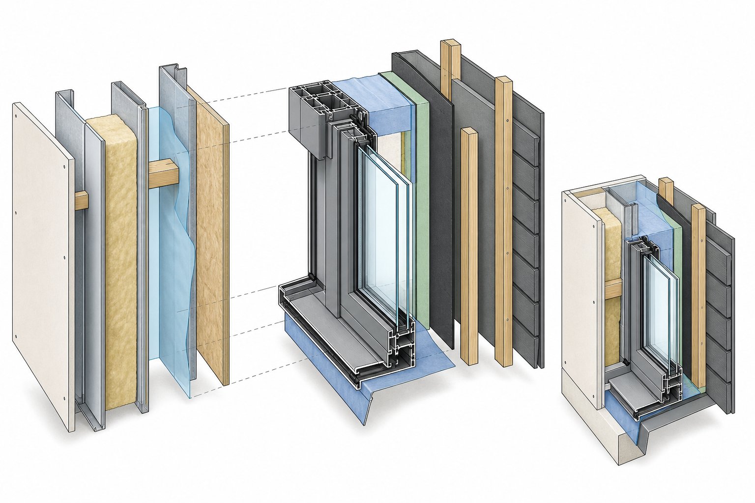
A window detail drawing of the jamb can look dense at first glance. Multiple material layers compressed into a single cross-section, each one annotated with a leader line pointing to something most people have never thought about. The reality is simpler than it appears. Every component falls into one of three functional groups: structure and fixing, sealing and moisture control, or finish and appearance. Once you understand those groupings, reading any aluminium drawing of a jamb condition becomes straightforward.
Here are the key components you will encounter on a typical window detail section, listed in order from interior to exterior:
- Plasterboard return or timber architrave (internal finish)
- Inner air seal (flexible sealant or compressed foam tape)
- Packing or shims (for plumb adjustment)
- Aluminium window frame profile (the extruded section)
- Fixing brackets or direct screw fixings (anchoring to structure)
- Insulation infill at the reveal gap
- Cavity closer or DPC (damp-proof course) membrane
- Outer weather seal (silicone or pre-compressed expanding tape)
- External cladding termination (render bead, brick return, or weatherboard)
Frame Profile and Fixing Method
The aluminium extrusion is the centrepiece of the detail. It is produced by forcing heated aluminium through a die to create the precise profile shape, including chambers for drainage, slots for glazing beads, and grooves for weatherstripping. Modern thermally broken profiles also incorporate a polyamide strip separating the interior and exterior faces of the frame, which shows up clearly in the cross-section as a darker band within the aluminium.
The frame anchors to the structural opening through one of two common methods. Direct screw-fix passes fasteners through the frame flange into the surrounding stud or masonry. Alternatively, galvanised steel brackets are fixed to the frame and then screwed back to the structure, allowing the window to sit forward in the insulation zone without thermal bridging through a solid fixing. Packing shims, usually plastic wedges, sit between the frame and the rough opening to achieve plumb alignment and maintain a consistent reveal gap.
Seal Lines and Moisture Barriers
Two distinct seal lines appear on a correctly drawn jamb detail. The inner seal sits on the room side and provides air tightness. It is typically a bead of flexible sealant or a compressed foam tape rated for interior conditions. The outer seal faces the weather and deflects bulk water. This might be a silicone bead, a pre-compressed expanding foam strip (such as ILLMOD or Tremco compriband), or a combination of both.
Between these two seals, the cavity closer or DPC membrane bridges the gap where the wall cavity meets the window reveal. Its job is to prevent moisture tracking from the cavity onto the window frame. In masonry cavity wall construction, this component is critical: it closes the cavity at the jamb while still allowing any trapped moisture to drain downward toward weep holes at the sill.
Internal and External Finishes at the Jamb
On the room side, the detail shows how the plasterboard or internal lining wraps around the reveal to meet the window frame. This might be a plastered return finished flush with the frame edge, or a timber architrave covering the junction. The gap between plasterboard and frame is sealed with the inner air seal mentioned above.
On the exterior face, the detail illustrates how the chosen cladding material terminates at the window. A brick return might stop 10 mm short of the frame with a sealant bead filling the gap. Rendered finishes typically use a PVC render stop bead at the frame edge. Weatherboard cladding calls for a scriber mould or cover flashing at the junction. Each approach creates a different reveal depth and visual shadow line, which is why the external finish must be resolved before the jamb detail can be finalised.
Dimensional tolerances and exact clearance measurements vary between window manufacturers and system series. Always cross-reference the specific extrusion dimensions and recommended installation gaps from the manufacturer’s technical data before setting these details in your construction documentation.
Jamb Details for Different Wall Construction Types
Every component described in the previous section still appears in the detail regardless of what the wall is made from. What changes is how those components relate to the structure behind them. A timber-framed house in coastal NSW, a steel-framed commercial fitout in Melbourne, a brick veneer home in suburban Brisbane, and a concrete apartment block in Perth each demand a different aluminium window jamb detail, even when the same window profile is specified across all four.
The differences come down to four variables: how the frame anchors to the structure, how deep the reveal is, how the cavity (if one exists) is managed at the jamb, and how flashing integrates with the weather-resistant barrier. Get any one of these wrong for the specific wall type and the detail fails in practice, no matter how tidy it looks on paper.
Timber Frame Jamb Details
Timber stud construction is the most straightforward jamb condition for residential aluminium windows in Australia. The frame typically screw-fixes directly through its flange into the timber jamb stud or a dedicated timber reveal lining. Fasteners are usually 10-gauge galvanised batten screws at 300 mm centres, biting into solid timber with at least 35 mm of thread engagement.
Reveal depth depends on the stud width and cladding system. A standard 90 mm stud with weatherboard cladding produces a relatively shallow external reveal of around 20 to 40 mm. With rendered fibre cement over a 90 mm frame, that reveal can be even less.
The weather-resistant barrier in a timber frame wall is the building wrap (typically a permeable membrane like a sarking product complying with AS 4200.1). At the jamb, this wrap must fold into the reveal and lap onto the face of the stud before the window is installed. The fold acts as a flashing, directing any water that penetrates the outer seal back to the outside of the wrap layer. Tape or fluid-applied flashing seals the wrap to the window frame after installation.
Steel Frame Jamb Details
Light-gauge steel framing changes the jamb detail in two significant ways. First, you cannot screw directly through an aluminium window flange into a thin steel stud and expect reliable long-term performance. The detail typically calls for galvanised steel jamb brackets or purpose-made window clips that fix to the steel stud with tek screws, then support the window frame on adjustable lugs. This bracket system also allows the window to sit forward in the insulation zone rather than hard against the steel.
Second, steel is a thermal conductor. Direct metal-to-metal contact between the aluminium frame and a steel stud creates a thermal bridge that shows up as condensation streaking on the internal reveal during winter. A compliant detail includes a thermal isolation pad, often a strip of closed-cell foam or a proprietary nylon isolator, between the bracket and the aluminium frame. Some specifiers also insist on a thermal break clip rather than a standard galvanised bracket.
Reveal depths in steel-framed construction tend to be shallower than timber because the stud is thinner (typically 64 mm or 75 mm for internal partitions, 92 mm for external walls). The flashing approach mirrors timber framing, with the WRB membrane folded into the reveal, but additional care is needed to seal around bracket penetrations through the membrane.
Masonry Veneer and Concrete Jamb Details
Brick veneer is arguably the most common external wall system in Australian residential construction, and its jamb detail is the most frequently misunderstood. The cavity between the brick skin and the structural frame must be closed at the window jamb without trapping moisture. A cavity closer, typically a DPC-backed rigid insulation unit or a folded damp-proof course membrane, bridges this gap. Masonry ties maintain the structural connection between the veneer and the backup frame in the courses adjacent to the opening.
The window itself usually fixes back to the timber or steel inner frame, not to the brickwork. This means the jamb detail must show the relationship between three elements: the brick return (which stops short of the frame to allow a sealant joint), the cavity closer (which prevents water migrating from the cavity onto the frame), and the fixing back to the structural stud behind. Reveal depth is typically deeper than in framed-only construction because the brick skin adds 110 mm plus the cavity width (usually 40 to 50 mm) to the overall wall thickness.
For full concrete or concrete block walls, the jamb detail shifts again. Windows can be cast-in using sub-frames placed before the pour, or post-fixed using chemical anchors or expansion bolts into the cured concrete. Cast-in methods provide tighter tolerances and better air sealing, but they require early coordination with formwork. Post-fixed installations offer flexibility for programme sequencing but need careful attention to sealant detailing because concrete surfaces are rarely perfectly flat or plumb. Flashing at the jamb in a concrete or CMU backup wall is typically a fluid-applied membrane dressed from the structural face onto the window frame, with insulation positioned outboard of the structure to minimise thermal bridging.
| Wall Type | Fixing Method | Typical Reveal Depth | Thermal Bridge Risk | Flashing Approach |
|---|---|---|---|---|
| Timber stud frame | Direct screw-fix through frame flange into stud | 20 – 40 mm (weatherboard); varies with cladding | Low (timber is a poor conductor) | Building wrap folded into reveal, taped to frame |
| Steel stud frame | Steel jamb brackets with thermal isolator pads | 15 – 30 mm (depends on cladding offset) | High (steel-to-aluminium contact) | WRB membrane into reveal; bracket penetrations sealed |
| Masonry veneer (brick) | Screw-fix to inner timber/steel stud; brick return with sealant joint | 50 – 90 mm (deep due to brick + cavity) | Medium (cavity closer interrupts bridging) | Cavity closer/DPC at jamb; sealant joint to brick return |
| Concrete / concrete block | Cast-in sub-frame or post-fixed with expansion bolts | Variable (depends on insulation placement) | High if uninsulated (concrete is conductive) | Fluid-applied membrane from structure face onto frame |
Each wall system introduces its own failure modes at the jamb. Timber frames can shrink and open seal joints over time. Steel frames bridge heat unless deliberately isolated. Masonry veneer traps water if the cavity closer is missing or installed flat rather than sloped outward. Concrete walls crack at fixing points when thermal cycling works on rigid anchors. A correct aluminium window jamb detail acknowledges these risks in its specification notes and provides the trades with enough information to manage them on site.
Building Code and Compliance for Jamb Installations
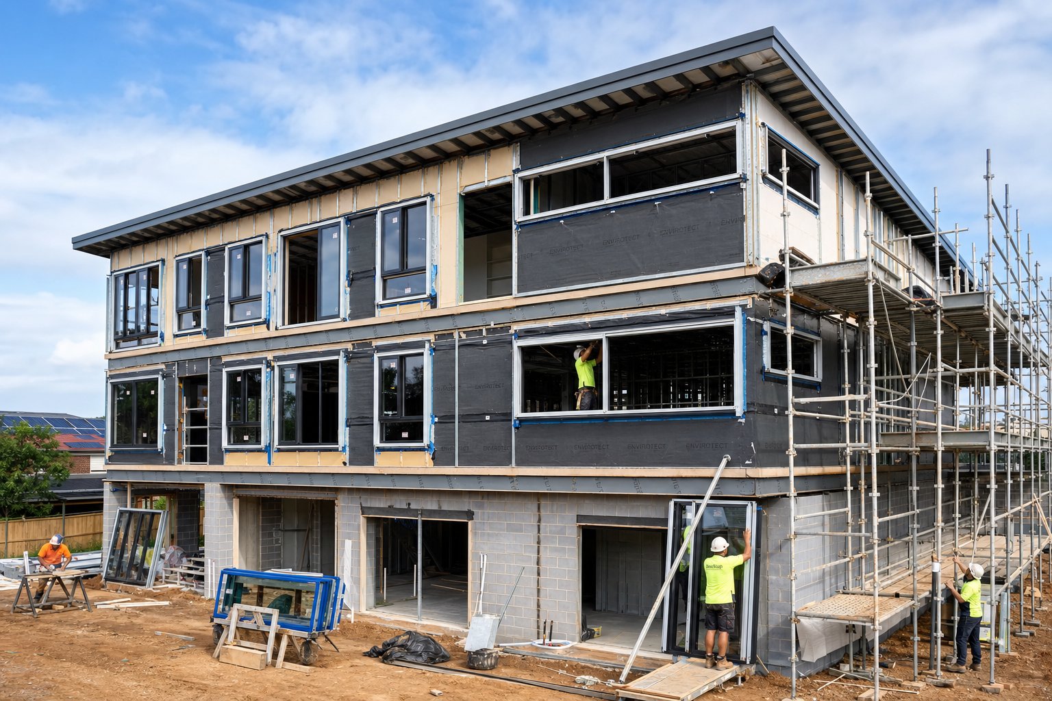
A jamb detail can look technically perfect on paper and still fail an inspection if it does not satisfy the regulatory framework governing window installations in Australia. The fixings, seals, and thermal provisions described in the previous sections are not optional design flourishes. They exist because Australian Standards and the National Construction Code mandate specific performance outcomes at the window-to-wall junction, and the jamb detail is the primary document proving those outcomes have been designed for.
Three key regulatory instruments shape how an aluminium window jamb detail must be drawn and built: AS 2047 (windows and external glazed doors), AS 4055 (wind loads for housing), and the NCC itself. Each addresses a different aspect of performance, but they overlap at the jamb because that junction simultaneously handles structural load transfer, water exclusion, and thermal regulation.
AS 2047 and Wind Load Compliance at the Jamb
AS 2047 is the national standard for windows and external glazed doors in Australia. It sets performance benchmarks for structural adequacy, water penetration resistance, air infiltration, and operating force. Every compliant aluminium window carries a performance label showing its wind and water ratings in Pascals, but the label only confirms the product itself was tested. How that product is fixed into the building is a separate compliance question, and the jamb detail is where the answer lives.
Wind pressure acts on the entire window surface and transfers through the frame into the fixings at the jamb, head, and sill. The fixing type, fastener diameter, and spacing shown on the jamb detail must be capable of resisting the design wind pressure for that specific location. AS 4055 classifies housing sites into wind regions (from A to D) and terrain categories, producing an ultimate design wind speed that feeds into the structural calculations. A window rated to N3 (for wind classification up to 41 m/s) installed in a region requiring N4 performance will not pass, regardless of how neatly the detail is drawn.
The ABCB Housing Provisions (Part 8.2) reinforce this by requiring that windows be installed so they resist design wind pressures and transfer resultant forces only to the adjacent framing members. They also mandate a minimum 10 mm gap between the top of the window assembly and any loadbearing element to prevent structural loads transferring into the frame. Packing at the jamb sides must keep the frame straight and be clear of any flashing material. These are not suggestions. They are Deemed-to-Satisfy provisions, and the jamb detail must reflect each one.
NCC Weatherproofing and Energy Requirements
Beyond structural performance, the NCC imposes weatherproofing and energy efficiency obligations that directly influence jamb detail design. The condensation management provisions (Part 10.8 in the Housing Provisions, formerly referenced under F6 in earlier NCC editions) require that building elements be designed to manage moisture vapour and surface condensation. At the jamb, this means the detail must show how the air seal prevents warm moist interior air from reaching cold surfaces within the frame cavity. Thermally broken aluminium profiles help here, but only if the surrounding detail maintains continuity of the thermal envelope.
Energy efficiency provisions under NCC Section J (commercial buildings) and Section 13 of the Housing Provisions (residential) set performance requirements for glazing and the building envelope that the jamb detail must support. Section J specifies maximum U-values and solar heat gain coefficients for glazing systems, while the housing provisions address building sealing and fabric performance. In both cases, the window frame and its junction with the wall form part of the thermal calculation. A frame fixed hard against a steel stud with no thermal isolator creates a conductive short circuit that undermines the energy model, regardless of how good the glass specification is.
The NCC also requires that external walls prevent water from penetrating to the interior. At the jamb, this obligation is met through the combination of outer weather seal, flashing integration, and drainage provision shown on the detail. A certifier reviewing documentation will look for evidence that these elements form a continuous barrier in conjunction with the head and sill details.
The following compliance checkpoints should appear on or be referenced by a compliant aluminium window jamb detail drawing:
- Window wind and water rating (Pascals) matching or exceeding the site-specific design pressures per AS 4055 and AS 2047
- Fixing type, size, and maximum spacing confirmed against the manufacturer’s installation manual for the rated wind load
- Minimum 10 mm clearance at head to prevent structural load transfer to the frame
- Packing locations at jamb sides positioned clear of flashing materials
- Inner air seal type and position (for condensation management and energy performance)
- Outer weather seal type, confirming compatibility with adjacent substrates
- Thermal break or isolation detail where frame contacts conductive structure
- Flashing membrane integration showing laps with head and sill flashings
- Reference to the manufacturer’s specific installation standard or guide
- Notation of the applicable NCC edition, AS 2047 compliance certificate number, and AS 4055 wind classification
Specific compliance values, R-value requirements, and U-value thresholds vary by NCC climate zone, building classification, and the current edition of each referenced standard. Always confirm these against the applicable regulatory documents at the time of design rather than relying on figures from earlier code cycles. The NCC is progressively tightening envelope performance targets, so a detail that satisfied the 2019 edition may fall short under more recent requirements.
Thermal Bridging and Energy Performance at the Jamb
The compliance requirements discussed above reference thermal breaks and isolation details for good reason. Aluminium conducts heat roughly 1000 times faster than timber, which makes it an outstanding structural material and a terrible insulator. Left unaddressed, this conductivity turns the aluminium window jamb into a thermal highway, funnelling energy straight through the building envelope at the exact point where wall insulation is interrupted by the window opening.
This phenomenon is called thermal bridging, and the jamb is where it does the most damage.
How Thermal Bridging Occurs at the Jamb
Picture the heat transfer path in cross-section. Warm interior air heats the inside face of the aluminium frame. That energy travels through the continuous aluminium extrusion toward the exterior face. At the jamb, the frame also contacts the structural opening through fixings, brackets, or packing. If the structure is steel or concrete, the heat has a second conductive path running laterally through the fixing and into the surrounding wall material.
The result is a localised cold spot on the internal frame surface during winter. Surface temperatures drop below the dew point of the indoor air, and condensation forms. Over time, that moisture damages paint finishes, promotes mould growth on adjacent plasterboard reveals, and degrades any timber components nearby. In summer, the same path works in reverse, conducting external heat into the conditioned space and forcing your cooling system to work harder.
Standard non-thermally-broken aluminium frames can have frame U-values exceeding 5.8 W/m²K. For context, that is roughly three to four times worse than a basic thermally broken system. The jamb junction amplifies this weakness because it adds structural fixings as additional conductive elements beyond the frame itself.
The jamb is often the weakest thermal point in the entire window assembly. While glass performance can be improved with coatings and gas fills, the jamb junction combines aluminium conductivity, structural fixings, and insulation discontinuity in a single narrow zone that most drawings fail to resolve adequately.
Thermal Break Solutions in Jamb Details
Modern aluminium window systems address this problem at three levels, and a correct jamb detail must show all three working together.
Within the frame profile: Polyamide thermal break strips (typically PA66 reinforced with 25% glass fibre) are mechanically crimped or rolled into the aluminium extrusion, physically separating the interior and exterior aluminium faces. On the jamb detail drawing, these show up as a distinct band, usually 14 mm to 35 mm wide, within the frame cross-section. The thermal conductivity of polyamide sits around 0.30 W/(m·K) compared to aluminium’s 160 W/(m·K), creating a dramatic reduction in heat flow through the profile.
Between frame and structure: Where the aluminium frame meets the surrounding wall, thermal isolation pads or proprietary nylon spacers prevent metal-to-metal contact. This is especially critical in steel-framed construction, but it also matters in concrete and masonry where metal brackets are used. On the detail drawing, look for a thin strip of closed-cell foam or a purpose-made nylon isolator between the fixing bracket and the frame flange.
Insulation continuity at the reveal: The gap between the window frame and the structural opening is typically 10 to 15 mm on each side. If this gap is left empty or packed only with shims, it becomes an uninsulated void that short-circuits the wall insulation. The detail should specify a low-expansion polyurethane foam or backer rod with sealant filling this gap, maintaining the thermal envelope continuously from wall insulation through to the frame’s thermal break.
When all three layers are correctly detailed and installed, frame U-values drop to the 1.2 to 2.0 W/m²K range for standard thermally broken systems, and below 1.0 W/m²K for premium multi-chamber profiles. This directly improves the whole-window U-value that feeds into NatHERS energy models and NCC Section J calculations for the building envelope.
Specifiers working to tight energy performance targets should request thermal modelling data from the window system supplier. Reputable manufacturers can provide two-dimensional thermal simulation results showing isotherms through the frame-to-wall junction, confirming that the specified jamb detail achieves the required performance under the project’s specific conditions. Without this data, the energy model relies on generic assumptions that may not reflect the actual installed detail.
Weatherproofing and Flashing Integration at the Jamb
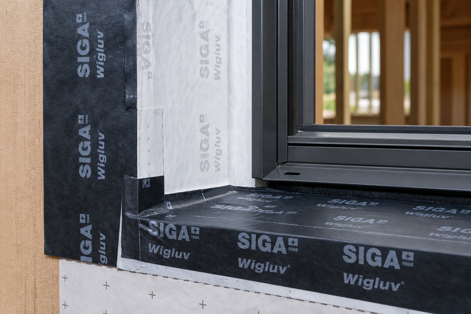
Thermal performance only matters if the wall stays dry. A jamb detail can incorporate every thermal break on the market, but once water finds its way past the outer seal and has no clear exit path, the insulation saturates, fixings corrode, and timber framing rots from the inside out. The aluminium window jamb detail must function as part of a continuous water management envelope that connects seamlessly with the head and sill flashings above and below.
Most construction drawings show the sealant joint at the jamb as a single line between frame and wall. That oversimplification is where failures begin. A robust weatherproofing strategy at this junction involves multiple layers working together: a flashing membrane dressed into the reveal before the window arrives on site, a dual-seal system managing both air and water independently, and a drainage pathway that allows any moisture breaching the first line of defence to escape downward without contacting building fabric.
Jamb Flashing Installation Sequence
Sequencing is everything with window flashing. Apply the membrane too late or lap it in the wrong direction, and you create a funnel rather than a barrier. The correct order of operations follows the fundamental rule of shingling: upper layers always lap over lower layers so gravity works with you rather than against you.
The installation sequence for jamb flashing on an aluminium window proceeds as follows:
- Prepare the structural rough opening. Check dimensions, confirm the opening is plumb and square, and ensure the substrate is clean, dry, and free of protruding fasteners or debris.
- Install the sill flashing first. This is the pan that catches any water draining down the jambs, so it must be in place before anything else. Turn the sill flashing membrane up at both jamb corners by a minimum of 150 mm to form dammed ends.
- Apply the jamb flashing membrane (self-adhesive tape or fluid-applied product) to both vertical sides of the rough opening. The jamb flashing must lap over the turned-up ends of the sill flashing at the bottom corners, creating a continuous water-shedding surface.
- Install the head flashing membrane across the top of the opening. Its lower edges must lap over the top of both jamb flashings. This ensures water running down from above is directed outward rather than behind the jamb membrane.
- Install the window into the prepared opening. Fix according to the manufacturer’s specifications, using appropriate packing at the jamb sides clear of the flashing material.
- Apply the outer weather seal (sealant bead or pre-compressed expanding tape) between the window frame and the external cladding or reveal face.
- Apply the inner air seal on the room side to complete the dual-seal envelope.
This sequence creates a continuous shingled envelope around the entire opening. Water hitting any point on the jamb flashing drains downward onto the sill pan and exits through weep slots or the unsealed bottom edge of the frame. Reversing any of these laps, particularly allowing head flashing to sit behind jamb flashing, directs water into the wall cavity rather than out of it.
Sealant and Drainage Design at the Jamb
The two-stage weatherproofing principle governs how sealant lines are positioned on a well-drawn aluminium window jamb detail. The concept is straightforward: the outer seal deflects bulk water (rain, wind-driven spray), while the inner seal provides air tightness. Between these two barriers sits a pressure-equalised cavity that allows any incidental moisture to drain freely without being pushed further inward.
On the exterior face of the jamb, the weather seal is typically a neutral-cure silicone sealant over a closed-cell polyethylene backer rod, or a pre-compressed expanding foam tape seated into a rebate in the frame profile. The backer rod serves two functions. It controls sealant depth to achieve the correct width-to-depth ratio (ideally 2:1 for movement joints), and it prevents the sealant from adhering to three surfaces, which would restrict its ability to stretch during thermal cycling. A bead that bonds on three sides tears rather than flexes.
The drainage path between the seals is critical yet often overlooked. Any water that bypasses the outer seal, whether through a pin-hole, an aged sealant crack, or capillary action, must have a clear route downward to the sill pan. The backer rod positioned close to the window flange should leave a small drainage gap against the frame, allowing moisture to track down rather than pooling in the cavity. At the sill, this water exits through designated weep holes or drainage slots in the bottom frame member.
On the interior side, the air seal prevents conditioned air from escaping and stops wind-driven pressure differentials from forcing moisture inward. This seal is less exposed to UV and weather, so acrylic-based sealants or purpose-made air-sealing tapes perform well here. The key requirement is continuity: the inner seal at the jamb must connect with the inner seal at the head and sill to form an unbroken air barrier loop around the entire window perimeter.
Sealant selection at both positions demands attention to substrate compatibility. Silicone adheres well to aluminium and glass but can stain porous masonry. Polyurethane sealants bond aggressively to most substrates but degrade under prolonged UV exposure unless painted or concealed. Hybrid polymer sealants offer a middle ground with good adhesion, paintability, and UV stability. The correct choice depends on the cladding material, exposure conditions, and whether the joint will be visible or concealed. Specific sealant and flashing product compatibility should always be confirmed with the window system manufacturer before specifying, as some aluminium finishes (particularly anodised surfaces) require primer coats for reliable adhesion.
When drawn correctly on the jamb detail, this two-stage system shows two distinct sealant lines, a backer rod profile at the outer seal, a clear cavity between, and flashing membrane extending from the structural face beneath both seal lines. Tradespeople reading the detail can see exactly where each material sits, what overlaps what, and which direction water flows when it enters the system. That clarity is the difference between a detail that performs for decades and one that starts leaking within its first winter.
How to Specify Aluminium Window Jamb Details on Drawings
Clarity on a detail drawing only counts if the right information is there in the first place. A beautifully drafted cross-section that omits fixing centres, sealant types, or flashing lap directions leaves the installer making assumptions, and assumptions at the jamb junction produce the failures covered throughout this article. Specifying an aluminium window jamb detail properly means treating the drawing and the written specification as two halves of a single instruction set. The drawing shows where everything goes. The specification says what it must achieve.
Essential Information on a Jamb Detail Drawing
A jamb detail drawing communicates spatial relationships and material positions to tradespeople who may never read the written spec. Every annotation must earn its place. Too few callouts and the installer guesses. Too many and the critical ones get lost in noise.
The following annotations should appear on every aluminium window jamb detail intended for construction documentation:
- Drawing scale (typically 1:5 for construction details, with 1:2 for complex junctions)
- Material callouts for every component visible in the cross-section, using standard hatching conventions
- Fixing type, fastener size, and maximum spacing (e.g. “10g x 65 mm galv. batten screw @ 300 mm max. centres”)
- Sealant types at both inner and outer seal positions, including backer rod diameter
- Flashing membrane extent, direction of laps, and minimum overlap dimensions
- Packing/shim locations and material type
- Thermal break or isolation pad position and material specification
- Reveal gap dimension and permissible tolerance range
- Insulation infill type at the frame-to-structure gap
- Reference notation pointing to the manufacturer’s installation manual (e.g. “Install per [Manufacturer] Technical Guide Rev. X, Section X.X”)
- Cross-reference tags linking to corresponding head, sill, and mullion details
- Key dimensions: frame setback from external face, reveal depth, and structural opening width
One common mistake is drawing the detail at too small a scale. At 1:10 or smaller, sealant lines merge visually with frame edges and flashing laps become illegible. Architectural documentation best practice recommends window junction details at 1:5 minimum, with enlarged portions at 1:2 where multiple seal lines or flashing laps overlap in tight spaces.
Written Specification Clauses Supporting the Detail
The drawn detail tells people what to build. The written specification tells them how well it must perform and what standards govern the work. These two documents must align perfectly. A spec clause calling for a window rated to N3 wind classification is meaningless if the jamb detail shows fixing centres only adequate for N2. Equally, a beautifully annotated detail is unenforceable without a specification clause that makes the manufacturer’s installation guide a contractual requirement.
Key specification clauses that support the jamb detail typically fall into three categories:
Performance requirements define what the installed assembly must achieve. These include wind load resistance (referencing AS 2047 and the site-specific wind classification per AS 4055), water penetration resistance in Pascals, maximum air infiltration rates, and thermal performance expressed as frame U-values or whole-window U-values for NatHERS or Section J compliance.
Installation standards and references establish the rules of workmanship. The specification should mandate installation strictly in accordance with the window manufacturer’s current technical manual, plus relevant Australian Standards such as AS 2047 for the product itself and the NCC Housing Provisions (Part 8.2) for installation requirements. Referencing the principle of connecting water, air, vapour, and thermal control layers from wall to window ensures the installer understands the hierarchy of priorities.
Quality assurance provisions create accountability. These clauses might require the installer to submit a method statement before commencing work, mandate hold-point inspections at the flashing stage (before windows are installed), and specify that a sample installation be completed and approved before the remainder proceeds. On larger projects, hose testing of a sample window to confirm water penetration resistance before fit-out begins is a common QA provision.
| Specification Clause | Aspect of Drawn Detail It Supports | Why Both Are Needed |
|---|---|---|
| Wind load performance (AS 2047 rating) | Fixing type, fastener size, and spacing at jamb | Drawing shows position; spec confirms the load it must resist |
| Water penetration resistance (Pa rating) | Outer seal type, flashing laps, drainage path | Drawing shows the system; spec sets the pass/fail pressure |
| Thermal performance (U-value) | Thermal break within profile, isolation pads, insulation infill | Drawing shows components; spec defines the target value |
| Manufacturer’s installation manual reference | All fixing, packing, and sealing positions | Drawing is a summary; the manual provides full procedural detail |
| Hold-point inspection at flashing stage | Flashing membrane extent and lap direction | Drawing shows correct laps; spec ensures they are checked before concealment |
| Air infiltration limit | Inner air seal type and continuity | Drawing shows seal location; spec quantifies acceptable leakage rate |
| Sealant compatibility and substrate preparation | Sealant type callouts at inner and outer positions | Drawing names the product; spec mandates primer and substrate prep |
Coordinating Jamb with Head and Sill Details
No jamb detail exists in isolation. It is one slice through a three-dimensional junction that also has a head condition above and a sill condition below. The flashing laps discussed in the previous chapter only work if the head, jamb, and sill details are read as a coordinated set. Head flashing must lap over jamb flashing. Jamb flashing must lap over the turned-up ends of the sill pan. Break any of those relationships and water enters the wall.
Architects should draw all three conditions (head, jamb, and sill) from the same project-specific wall build-up, not from generic library details that may not reflect the actual construction. Window detailing guides consistently emphasise that the three details must use the same scale, the same annotation conventions, and cross-reference each other with clear drawing tags. Where mullion conditions exist (vertical divisions between adjacent window panels), a fourth detail is required showing how the mullion section relates to the jamb framing and how flashing continuity is maintained across the junction.
A practical coordination check before issuing construction documents: lay the head, jamb, and sill details side by side and trace the four control layers (water, air, vapour, thermal) through all three. Each layer should be continuous and unbroken as it transitions from one detail to the next. If any layer terminates without a clear connection to the adjacent detail, there is a gap in the design that will become a gap in the building.
Getting the specification and drawing coordination right at this stage prevents the far more expensive exercise of diagnosing failures after the wall is closed up. It also gives the certifier, builder, and window installer a single coherent instruction set rather than a collection of disconnected drawings that each tell a slightly different story about how the window meets the wall.

Selecting the Right Aluminium Window Profile System
Everything covered so far, fixings, seals, thermal breaks, flashing sequences, assumes you have already chosen a window system. In practice, the profile system you select determines the jamb detail rather than the other way around. Different aluminium window manufacturers use different extrusion depths, fixing methods, and thermal break configurations, and each of those variables reshapes the cross-section drawing your builder works from on site.
How Profile Systems Affect Jamb Design
A residential series window built on a 50 mm platform produces a slim frame that sits shallow in the wall, resulting in a narrow reveal and straightforward direct screw-fix detail. Step up to a semi-commercial system on a 100 mm platform and the extrusion depth nearly doubles. The frame projects further into the structural opening, reveal geometry changes, and the fixing method may shift from face-fix screws to rear-mounted brackets to accommodate the deeper profile.
Commercial-grade systems introduce another layer of complexity. As AWS Australia notes, true commercial windows and doors require installation using sub-head and sub-jamb details to achieve their rated performance. These sub-frames create a secondary structural sleeve within the rough opening before the window itself is installed. The jamb detail for a commercial system therefore shows two aluminium sections rather than one: the sub-jamb fixed to the structure, and the window frame clipped or screwed into the sub-jamb. Residential systems skip this step entirely, fixing directly to the wall framing.
Thermal break configuration also varies by system series. Entry-level residential profiles may omit thermal breaks altogether. Mid-range systems incorporate a single polyamide strip, typically 14 to 20 mm wide. High-performance series use wider strips, sometimes 35 mm or more, or multi-chamber polyamide sections that dramatically lower the frame U-value. Each configuration produces a visually different cross-section on the jamb detail and changes how the thermal control layer connects from wall insulation through to the frame.
Matching the Right System to Your Project
Choosing a profile system is not purely an aesthetic decision. The jamb detail must resolve structural loads, thermal targets, and weatherproofing simultaneously, and some systems handle certain conditions better than others. Match your selection to the project constraints rather than forcing a detail to work with a system that was never designed for those conditions.
Key selection criteria for choosing an aluminium window system based on jamb detail requirements:
- Wind rating: confirm the system series is rated to the design wind pressure for your site per AS 4055, including adequate fixing capacity at the jamb
- Thermal performance targets: select a thermal break width and profile configuration that achieves the frame U-value needed for NatHERS compliance or NCC Section J calculations
- Construction type compatibility: verify the manufacturer provides tested jamb details for your specific wall build-up (timber frame, steel frame, masonry veneer, or concrete)
- Reveal depth and aesthetic preference: deeper profiles create bolder shadow lines but reduce glazing area; slimmer systems maximise glass but may limit wind rating
- Glazing capacity: ensure the frame can accommodate the glass thickness required (single, double, or triple glazing) without compromising the jamb seal geometry
- Manufacturer documentation: prioritise systems that supply project-ready installation details, certified performance data, and technical support for specifiers
That last point deserves emphasis. A window system backed by comprehensive manufacturer documentation saves hours of design time and reduces installation risk. Rather than drafting jamb details from scratch, specifiers can adapt manufacturer-provided typical details to suit project-specific wall constructions, confident that the underlying system has been tested to perform as drawn.
For readers exploring systems suited to Australian residential and commercial builds, MEICHEN’s aluminium window range offers project-ready specifications, custom profile options, and installation documentation designed for local construction types and compliance requirements.
Whichever system you select, request the full technical detail set early in design development, not after the wall framing is up. The aluminium window jamb detail flows from the profile geometry, and the profile geometry is locked in the moment you choose a system series. Getting that decision right at the specification stage means your drawings communicate a buildable, compliant junction that performs for the life of the building.
Frequently Asked Questions About Aluminium Window Jamb Details
1. What is included in an aluminium window jamb detail drawing?
A compliant aluminium window jamb detail drawing includes the aluminium frame profile cross-section, fixing type and spacing, inner air seal and outer weather seal positions, flashing membrane extent and lap directions, packing locations, thermal break or isolation pad specifications, reveal gap dimensions, insulation infill type, and reference to the manufacturer’s installation manual. It should be drawn at a minimum scale of 1:5 and cross-reference corresponding head, sill, and mullion details to form a complete installation instruction set.
2. Why is thermal bridging a problem at the aluminium window jamb?
Aluminium conducts heat roughly 1000 times faster than timber, making the jamb junction a weak point in the building envelope. Heat transfers through the continuous aluminium extrusion and through structural fixings into the surrounding wall, creating localised cold spots that cause condensation, mould growth, and increased energy costs. Modern thermally broken profiles use polyamide strips to separate interior and exterior aluminium faces, while isolation pads between the frame and structure prevent metal-to-metal contact. Without these measures, frame U-values can exceed 5.8 W/m2K, significantly undermining energy performance targets required under NCC Section J and NatHERS modelling.
3. How does the aluminium window jamb detail differ between timber frame and brick veneer walls?
In timber frame construction, the aluminium window typically screw-fixes directly through its flange into the timber jamb stud, with building wrap folded into the reveal as the weather-resistant barrier. Reveal depths are relatively shallow at 20 to 40 mm. Brick veneer construction is more complex because the cavity between the brick skin and the structural frame must be closed at the jamb using a DPC-backed cavity closer. The window fixes back to the inner timber or steel stud rather than the brickwork, and reveal depths are significantly deeper at 50 to 90 mm due to the added brick and cavity width.
4. What is the correct flashing sequence for an aluminium window jamb installation?
The correct sequence follows shingling principles where upper layers always lap over lower layers. First, prepare and check the structural rough opening. Second, install the sill flashing pan with ends turned up at least 150 mm at both jamb corners. Third, apply jamb flashing membrane to both vertical sides, lapping over the sill flashing turn-ups. Fourth, install head flashing lapping over the top of both jamb flashings. Fifth, fix the window into the prepared opening. Finally, apply the outer weather seal followed by the inner air seal. Reversing any lap direction, particularly allowing head flashing behind jamb flashing, directs water into the wall cavity.
5. Which Australian Standards apply to aluminium window jamb installations?
Three key regulatory instruments govern aluminium window jamb installations in Australia. AS 2047 covers performance benchmarks for structural adequacy, water penetration resistance, and air infiltration of windows and external glazed doors. AS 4055 classifies wind loads for housing sites based on wind region and terrain category, determining the design wind pressure that fixings at the jamb must resist. The National Construction Code (NCC) imposes weatherproofing requirements, condensation management provisions, and energy efficiency targets under Section J for commercial buildings and Section 13 of the Housing Provisions for residential. Compliance values vary by climate zone and NCC edition, so specifiers should confirm against current documents.
More Window & Door Guides