
What Aluminium Window Flashing Does and Why It Matters
Aluminium window flashing is a pre-formed metal component installed around window openings to divert bulk water away from vulnerable joints in the building envelope. It bridges the gap between the window frame and the surrounding wall, maintaining continuity of the drainage plane so moisture never reaches the structural framing, insulation, or internal linings behind your cladding.
Every window starts as a hole in the wall. That opening creates a three-dimensional interruption in what would otherwise be a continuous water-shedding surface. Window flashing exists to manage this interruption by collecting any water that reaches the frame-to-wall junction and directing it safely outward and downward. In both residential homes and commercial builds across Australia, properly detailed flashing for windows prevents the silent damage that sealant alone simply cannot stop.
What Is Aluminium Window Flashing
Put simply, any durable, impervious material installed to redirect water away from a sensitive area qualifies as a flashing. Aluminium window flashing specifically refers to brake-formed or extruded aluminium profiles shaped to fit head, jamb, and sill locations around a window assembly. Its job breaks down into three functions: divert water that reaches the frame perimeter, maintain unbroken connection with the weather-resistive barrier (WRB), and prevent moisture ingress behind the cladding system.
Unlike flexible tapes or liquid-applied membranes, aluminium holds its shape permanently. It resists UV degradation, tolerates Australia’s extreme temperature swings without softening, and provides a rigid drip edge that physically breaks the surface tension of running water. These properties make it the preferred choice for flashing on windows in exposed locations, high-rise applications, and anywhere long-term serviceability matters more than speed of installation.
Why Metal Flashing Outperforms Sealant-Only Methods
Relying on caulk or sealant as a substitute for flashing is one of the most common shortcuts in residential construction. Sealant joints degrade under UV exposure, shrink as they cure, and eventually crack with thermal movement. A bead of silicone across a window-to-wall joint might last five to seven years before it fails. An aluminium flashing detail, installed correctly, will outlast the window itself.
Metal flashing also outperforms flexible membrane tapes in specific scenarios. On sun-exposed north and west elevations common to Australian homes, self-adhered tapes can soften and creep. In coastal environments from the Gold Coast to Fremantle, salt-laden air accelerates adhesive breakdown. Aluminium provides a mechanical, gravity-driven solution that does not rely on adhesion chemistry to perform. This makes it the superior option for flashing windows in demanding climates where flexible products lose their bond over time.
Core Principles of Water Management at Windows
Regardless of how complex a wall assembly becomes, effective window flashing rests on two foundational principles that apply to every detail around the perimeter:
Principle 1: WRB Integration — Every flashing component must tie into the weather-resistive barrier so that water intercepted at the window is handed off to the drainage plane without interruption.
Principle 2: Shingle-Fashion Lapping — Each layer overlaps the one below it, ensuring water always travels over (never behind) the next surface down. Lower elements install first; upper elements lap over them.
These two rules govern the sequence, geometry, and overlap dimensions of every aluminium flashing detail discussed throughout this guide. Violate either one, and water finds a path inward regardless of how high-quality the materials are. The next consideration is understanding which profile shape belongs at each location around the window — a decision driven by both the physics of water movement and the specific cladding system in play.
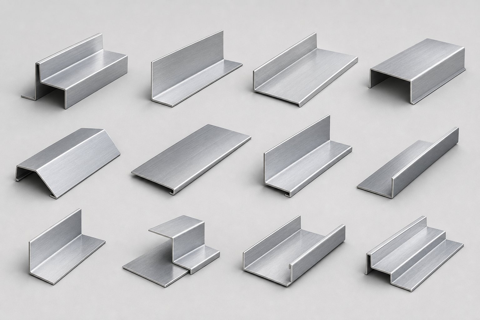
Aluminium Flashing Profile Types and Where Each One Belongs
Each location around a window opening faces a different water management challenge. The head deals with cascading runoff from the wall above. The sill must collect and drain water that penetrates past the frame. Jambs handle lateral migration driven by wind pressure and capillary action. A single profile shape cannot address all three — which is why aluminium flashing comes in distinct profile types, each engineered for a specific position and a specific physics problem.
Choosing the right metal flashing for windows is not a matter of preference. It is a matter of matching form to function. The profile’s geometry determines whether it creates an adequate capillary break, manages surface tension at the drip point, and relieves hydrostatic pressure at corners where water tends to accumulate. Below is a breakdown of the six most common profiles and the logic behind selecting each one.
Z-Bar and L-Shaped Flashing Profiles
A Z-bar profile, viewed from the side, forms the shape of the letter Z. It consists of three planes: an upper leg that tucks behind the cladding or WRB above, a horizontal bridge that spans the transition, and a lower leg that laps over the surface below. This geometry makes it ideal for horizontal junctions where two different materials or planes meet at the same elevation — particularly common at mid-height cladding joints near window heads on fibre cement or weatherboard homes.
The critical dimension on a Z-bar is the horizontal bridge. If it is too narrow, capillary action draws water across the gap rather than allowing it to drop free. A minimum bridge width of 10 mm creates an effective capillary break for most residential applications. Wider bridges — 15 mm to 20 mm — suit exposed elevations or locations with high wind-driven rain loads, such as coastal Queensland or the southern Victorian coast.
L-shaped profiles are simpler. One leg sits vertically behind the cladding; the other extends horizontally. Step flashing is a common L-shaped variant used where a sloping roof plane meets a wall beside a window. Each piece overlaps the one below in shingle fashion, shedding water progressively downward. For window jamb locations, an L-profile can serve as a turned-edge detail that directs water away from the vertical joint between the window frame and the adjacent wall.
- Z-bar selection criteria: Horizontal material transitions near window openings; situations requiring a capillary break across a plane change; cladding systems with a butt joint at window head height.
- L-shaped selection criteria: Roof-to-wall junctions adjacent to windows; simple right-angle transitions at jambs; stepped overlapping sequences along inclined surfaces.
Drip Caps and Head Flashing Profiles
A drip cap sits directly above the window head. Its job is straightforward but essential: intercept water running down the wall face and throw it clear of the window frame below. The profile typically forms an L-shape or a shallow Z, with the upper leg tucking behind the cladding or WRB and the lower leg projecting outward beyond the face of the window trim.
What makes a drip cap work is the projected drip edge. As water runs along the underside of the lower leg, surface tension wants to pull it back toward the wall. A formed kick — a small downward bend at the outermost edge — breaks that surface tension and forces the water to release as a drip. Without this detail, water wraps around the profile and runs directly onto the window head flashing joint, eventually finding a path inward.
Drip cap dimensions matter. For most Australian residential builds, the projection beyond the face of the cladding should be a minimum of 10 mm to 15 mm to be effective. In areas subject to heavy driving rain, 20 mm provides an additional safety margin. The upper tuck-in leg should extend at least 50 mm behind the WRB to prevent back-splash or wind-driven spray from bypassing the profile.
- Drip cap selection criteria: Required at the head of every window without an integrated head drip; essential on exposed elevations without eave protection; critical where cladding does not extend over the window head to shed water naturally.
Pan Flashing and Subsill Systems
The sill is where failures concentrate. Water that breaches the primary seal between frame and wall, or condensation that forms on the interior face of the glass and drains downward, has nowhere to go unless a pan flashing catches it. A window pan flashing is essentially a shallow tray installed beneath the window unit, designed with a back dam to prevent inward drainage, end dams at each side to block lateral migration, and a front edge that laps over the WRB below so collected water exits to the exterior.
Building Science Corporation identifies four essential characteristics every pan flashing must have: a continuous waterproof surface without holes or wrinkles, a back dam or positive slope directing water outward, end dams preventing lateral movement into the wall, and proper lapping over the drainage plane beneath the opening. These principles hold whether the pan is formed from sheet aluminium, a self-adhered membrane, or a manufactured two-piece system.
A subsill system takes the concept further. Rather than a field-formed tray, a subsill is a pre-manufactured aluminium profile — often extruded — that clips or screws to the rough opening before the window is set in place. It provides built-in slope, defined drainage channels, and factory-consistent end-dam heights. Subsill systems are increasingly specified in commercial construction and higher-end residential projects across Australia because they eliminate the variability of site-formed alternatives.
Window corner flashing details at the sill are the most demanding to get right. The junction between the end dam and back dam of a sheet metal pan should be folded — not cut and sealed — to create a durable, watertight corner. Cut corners rely on sealant at exactly the spot where water pressure is highest, which is a recipe for eventual failure.
- Pan flashing selection criteria: Every window opening in a drained wall assembly; particularly critical at sill locations below operable windows where frame seals are more prone to leakage; essential in high-rainfall climate zones.
- Subsill selection criteria: Commercial projects requiring repeatable quality; residential builds targeting higher performance standards; retrofit scenarios where integrating a field-formed pan is impractical.
| Profile Name | Location on Window | Primary Function | Typical Dimensions |
|---|---|---|---|
| Z-Bar | Head area or horizontal cladding transitions near window | Creates capillary break across plane changes; sheds water at material junctions | Bridge width 10–20 mm; legs 30–50 mm each |
| L-Shaped / Step | Jambs; roof-to-wall junctions adjacent to windows | Directs water away from vertical joints; shingle-laps along inclined surfaces | Each leg 75–100 mm; overlap 50 mm minimum per step |
| Drip Cap | Head (above window frame) | Intercepts wall runoff; throws water clear of window head via drip edge | Projection 10–20 mm beyond cladding face; upper leg 50 mm+ behind WRB |
| Pan Flashing | Sill (beneath window frame) | Collects water penetrating frame seal; drains it outward over WRB below | Back dam 25–40 mm high; end dams 25–50 mm; slope minimum 6 degrees |
| Stepped Flashing | Jambs along sloped roof-to-wall junctions | Progressively sheds water down slope in overlapping sequence | Individual pieces 100 × 200 mm typical; 50 mm overlap per course |
| Subsill (Extruded) | Sill (pre-manufactured tray beneath window) | Provides factory-consistent slope, drainage channels, and end dams | Varies by manufacturer; back dam typically 30–50 mm; integrated drainage weeps |
Profile selection is the starting point, but a perfectly shaped piece of metal window flashing still fails if it is made from the wrong alloy, pressed to the wrong thickness, or finished with a coating that cannot handle local conditions. The material behind the profile matters just as much as the profile itself.
Material Specifications for Aluminium Flashing Selection
A drip cap or pan flashing can have textbook geometry and still fail prematurely if the material itself cannot handle the environment. Alloy composition determines corrosion resistance. Thickness governs rigidity and resistance to deformation. Surface finish dictates UV longevity and aesthetic compatibility with the cladding. These material decisions deserve the same attention as the profile shape, yet they rarely receive it in standard project documentation.
Alloy and Temper Selection for Flashing
Most aluminium flashings supplied into Australian residential projects use alloy 3003, a manganese-based composition offering good formability and adequate corrosion resistance for sheltered to moderate exposures. It bends cleanly in a brake press without cracking and holds its shape once formed, making it a practical default for general-purpose window metal flashing in suburban builds away from the coast.
Coastal and high-exposure environments demand more. Alloy 5005 uses magnesium as its primary alloying element, delivering superior corrosion resistance and — critically — a smooth, uniform surface when anodised. Where aluminium flashings will be visible on the finished elevation, 5005 produces consistent colour matching that 3003 cannot achieve. It is the preferred alloy for architectural-grade aluminium flashing for windows in salt-air zones from Cronulla to Cottesloe, and anywhere the flashing remains exposed to view.
Temper designation controls hardness and formability. H32 (strain-hardened, then stabilised) provides a useful middle ground — stiff enough to hold a formed drip edge without springing back, yet soft enough to allow field bending without fracture. H14 offers slightly higher stiffness for pre-formed components. For complex profiles requiring tight radii, ordering in O temper (fully annealed) and accepting lower rigidity may be necessary. These temper designations conform to ASTM B209, the governing standard for aluminium sheet and plate used in construction applications.
| Alloy | Best Use Case | Corrosion Resistance | Formability |
|---|---|---|---|
| 3003-H32 | General residential flashing; sheltered to moderate exposure | Good — adequate for inland and suburban locations | Excellent — bends cleanly without cracking at standard radii |
| 5005-H32 | Coastal, anodised, or architecturally exposed flashing | Very good — magnesium content resists salt-air degradation | Good — slightly firmer than 3003 but handles standard bends well |
| 5052-H32 | High-strength commercial applications; marine environments | Excellent — highest corrosion performance in the 5xxx series | Moderate — tighter bend radii may cause cracking; best for simple profiles |
Gauge and Thickness Requirements by Application
Thickness determines whether a formed flashing holds its intended shape under wind load, thermal cycling, and the physical stresses of installation. Too thin, and the material oil-cans — developing visible ripples across flat faces that look poor and can trap water. Too thick, and field forming becomes difficult without industrial brake equipment.
For residential window aluminium flashing, 0.5 mm to 0.9 mm covers most applications. A 0.7 mm sheet balances formability with rigidity for typical head flashings and pan details. Commercial projects and institutional buildings generally step up to 1.2 mm or thicker. Western Washington University’s campus construction standards specify a minimum 0.050 inch (1.27 mm) for all aluminium flashings — a practical benchmark for any commercial specification in Australia.
The NRCA (National Roofing Contractors Association) recommends a minimum of 0.032 inch (0.81 mm) for aluminium counterflashings used in low-slope applications. While Australian projects reference AS 2904 for damp-proofing and flashing in buildings, the dimensional logic holds: thicker metal for larger exposed faces, thinner stock where profiles are concealed and face dimensions remain small.
- 0.5 mm: Concealed flashings with small face dimensions (under 75 mm exposed); budget residential where appearance is not critical.
- 0.7 mm: Standard residential window head, jamb, and pan flashings; most common thickness for aluminium flashing windows in Australian housing.
- 0.9 mm: Exposed flashings on elevations without eave protection; larger face dimensions (75–150 mm exposed) where oil-canning resistance matters.
- 1.2 mm+: Commercial and institutional projects; high-wind zones; flashings with exposed face dimensions exceeding 150 mm.
Finish Options and Their Performance Characteristics
Mill finish aluminium — the raw, uncoated surface straight from the rolling mill — develops a natural oxide layer that provides basic corrosion protection. It weathers to a dull grey over time. For concealed flashings that no one will see once the cladding is installed, mill finish is perfectly adequate and the most economical choice.
Anodising builds on that natural oxide by electrochemically thickening it to 15–25 microns, creating a hard, scratch-resistant surface that accepts consistent colour. Anodised finishes suit architecturally exposed aluminium flashings in clear, bronze, or charcoal tones. They pair well with anodised window frames, providing a seamless visual transition. The alloy matters here — 5005 anodises uniformly, while 3003 can produce a mottled, streaky appearance.
Polyester powder coating offers a broader colour palette and good UV resistance for 10 to 15 years in moderate climates. It bonds mechanically to the aluminium surface and works well for matching Colorbond or similar pre-finished cladding systems. For maximum durability in harsh Australian UV, PVDF (polyvinylidene fluoride) coatings — often marketed under the Kynar brand — deliver 20+ years of colour retention and chalk resistance. PVDF is the standard for premium commercial projects where long maintenance cycles are essential.
Compatibility matters as much as longevity. Powder-coated flashings should not contact wet mortar or fresh concrete, which is alkaline enough to attack the coating. Anodised surfaces tolerate alkaline contact better but still benefit from isolation where render is applied directly against the flashing. The finish you select needs to work with the adjacent materials, not just withstand the weather — a consideration that leads directly into how these flashings perform dimensionally once installed and subjected to real thermal loads.
Head and Jamb Flashing Details with Dimensional Guidance
Finish compatibility determines whether a flashing survives contact with its neighbours, but the real question is whether its dimensions prevent water from reaching those neighbours in the first place. Every millimetre in a window head flashing detail serves a purpose rooted in physics — surface tension, capillary action, wind pressure, and the behaviour of water running down a vertical surface under gravity. Get the numbers wrong, and even the best alloy in the best finish will preside over a leak.
Head Flashing Dimensions and Drip Edge Design
Head flashing for windows sits above the frame and performs two jobs simultaneously: it deflects water running down the wall face, and it drains any moisture that has already entered the cavity behind the cladding. The critical dimensions governing both functions are the upstand height, the drip edge projection, and the cross-fall angle.
Minimum upstand height: 50 mm behind the cladding line. This dimension prevents wind-driven rain and back-splash from overtopping the flashing and entering the wall cavity above the window. In extra-high wind zones, increase to 60 mm with a hooked or hemmed edge for additional security.
Why 50 mm? Water striking a wall surface rebounds. Droplets splash upward as much as 30 mm to 40 mm from a direct hit on the cladding face. A 50 mm upstand provides adequate freeboard above that splash zone, ensuring water cannot jump over the flashing’s back leg and wet the framing above. BRANZ research confirms that cladding must cover a minimum 35 mm of the flashing upstand — or 60 mm with a hook in extra-high wind zones — to maintain reliable weather protection at the head.
The drip edge projection needs to throw water clear of the window frame below. A minimum of 10 mm beyond the face of the window flange is the baseline, though 15 mm to 20 mm provides a better margin on exposed elevations without eave protection. The physics here involves surface tension: water running along the underside of a horizontal surface clings to that surface rather than dropping free. A formed kick-out — a small downward bend at the outermost edge of the projection, typically 5 mm at a 45-degree angle — breaks that surface tension and forces a clean drip release.
Cross-fall matters too. Flashing over windows should slope outward at a minimum of 15 degrees. This prevents water from pooling on the flat surface during high-intensity rain events. A level flashing allows a film of water to build depth, increasing hydrostatic pressure at any imperfection in the overlap or joint. The 15-degree fall ensures continuous drainage under gravity alone.
Where the front downturn of the head flashing meets the window frame, two approaches exist. The first — and in practice, the more reliable — has the downturn fitting firmly over the top window flange. This eliminates any gap for wind-driven water to exploit. The alternative positions the downturn forward of the flange, creating a small overhang. If this approach is used, industry guidance limits the gap to a maximum of 9 mm. Larger gaps allow wind pressure to drive water upward over the flange during storms. In very high and extra-high wind zones, sealant between the underside of the head flashing and the top edge of the window flange becomes mandatory regardless of which option is selected.
Jamb Flashing Integration and End Dam Details
Jamb flashings manage lateral water movement — the sideways migration of moisture driven by wind pressure or drawn by capillary forces along horizontal surfaces. End dams are the critical element here: small vertical turn-ups at each end of the head flashing that prevent water from running off the ends and behind the jamb cladding.
End dam height should match or exceed the upstand height at the back of the head flashing. A 10 mm turn-up — the minimum dimension referenced in cavity-construction details — prevents water from overflowing at the flashing ends when the cavity is draining properly. However, this dimension assumes low water volumes. For windows beneath large wall areas with significant catchment, or where multiple storeys of cladding drain to a single head flashing, increasing end dams to 20 mm to 25 mm provides a sensible margin against overflow during peak rainfall events.
End dams should terminate at the inside face of the cladding in cavity wall systems. They do not pass through the cladding. This keeps the drainage path within the cavity — water hits the end dam, is redirected back toward the front of the flashing, and drains out via the 5 mm ventilation gap maintained between the bottom edge of the cladding course and the top of the flashing.
At direct-fixed cladding installations (no cavity), the approach differs. A 50 mm bead of sealant between the cladding and each end of the head flashing replaces the physical end dam as the moisture barrier at the termination points. This detail requires careful workmanship — the sealant must be continuous with no voids, and it needs to bond cleanly to both the aluminium and the cladding substrate.
The window header flashing detail must also account for how jamb flashings integrate vertically. The head flashing’s drip projection should extend a minimum of 20 mm past the vertical edge of the side flange or jamb scriber. This ensures water dripping off the head falls clear of the jamb junction rather than tracking down the vertical joint where it can enter behind the frame.
Bridging the Gap Between Manufacturer Specs and Field Requirements
Window manufacturers provide installation instructions focused on securing their product in the opening. They specify fixing centres, shim placement, and frame-to-reveal tolerances. What they rarely detail is the supplemental head flashing windows actually need to perform in a complete wall assembly — the field-installed components that sit outside their scope of supply but are essential to weathertightness.
This creates a responsibility gap. The window maker assumes the builder will provide correct flashings. The builder assumes the window installation instructions cover everything. Neither party explicitly owns the window flashing detail at the head-to-jamb transition. The result, on too many Australian building sites, is improvisation — or worse, omission.
Supplemental details that sit outside standard manufacturer instructions but remain essential include:
- Flexible flashing tape bridging between the head flashing upstand and the WRB above — creating the weather-resistive barrier connection that shingle-laps over the rigid metal flashing.
- Corner treatment at the junction of the head flashing end dam and the jamb flashing below — where a folded or lapped membrane must create a continuous watertight corner.
- A drainage ventilation gap between the bottom of the cladding and the top of the head flashing — typically 5 mm — that allows the cavity to breathe and drain without trapping moisture against the flashing surface.
- Sealant between the head flashing underside and the top window flange in high-wind-zone applications, which is not part of the window installation sequence but is critical to preventing wind-driven water ingress.
The correct installation sequence at the head-to-jamb junction follows a strict lapping order. Each step ensures that water hitting any surface is always directed outward and downward, never given a path inward:
- Install the WRB (wall underlay) across the full wall, cutting and folding it into the rough opening at the head.
- Install jamb flashings (flexible membrane or rigid aluminium angle) running from below the sill to above the head location, lapping over the WRB at the jamb faces.
- Set the window into the prepared opening per manufacturer instructions.
- Install the rigid aluminium head flashing with its end dams sitting over the top of the jamb flashings, ensuring the drip edge projects at least 20 mm past the jamb line.
- Apply flexible flashing tape over the head flashing upstand, extending onto the WRB above and lapping over the top edges of the jamb membrane — this is the final shingle layer that ties the entire assembly back into the drainage plane.
Step 5 is the one most frequently missed on site. Without it, water behind the cladding above the window runs straight behind the rigid head flashing rather than draining over its face. That single omission converts a well-detailed window flashing into a funnel directing water exactly where it should never go.
Getting these dimensions and sequences right at the head and jambs solves the upper half of the window perimeter. The lower half — the sill — is where failures concentrate most heavily, because it must collect everything the rest of the assembly cannot fully divert, and drain it before any accumulation reaches the framing.
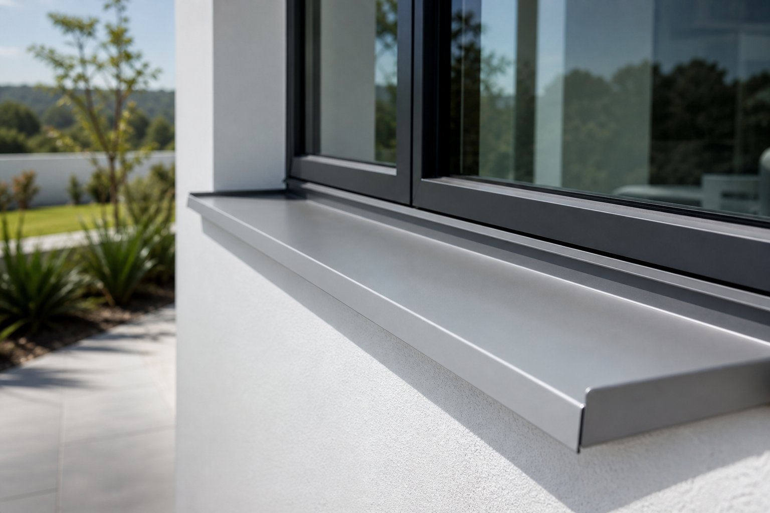
Sill and Sub-Sill Pan Flashing That Prevents Water Ingress
The sill collects everything. Water that breaches the primary frame seal, condensation running down the interior glass face, wind-driven spray that bypasses the head and jamb flashings — all of it ends up at the lowest point of the window opening. Forensic building envelope investigations consistently identify improper window sill flashing as the number one source of window leaks, ahead of head flashings, jamb failures, and sealant breakdown combined. The reason is simple: gravity delivers water here relentlessly, and any deficiency in the sill detail becomes a direct path into the wall framing.
Unlike the head, where flashing primarily deflects, sill flashing for windows must perform three sequential functions. It must collect infiltrated water, contain it within a defined space, and then evacuate it to the exterior before it reaches the rough opening timbers. Fail at any one stage and moisture accumulates in exactly the location where framing is most vulnerable to decay.
Divert, Drain, Dry — Every sill pan assembly must divert water away from the frame-to-structure interface, drain collected moisture outward through defined paths, and allow residual dampness to dry through ventilation. If any one of these three functions is compromised, the window sill flashing detail becomes a concealed reservoir rather than a drainage device.
Sill Pan Flashing Design and Slope Requirements
An aluminium sill pan sits beneath the window frame, forming a waterproof tray that intercepts any moisture passing the primary seal. Its geometry must include a back dam rising up behind the window frame, end dams at each side preventing lateral escape, and a front edge that laps over the weather-resistive barrier below the opening. The front edge is the drainage outlet — water that reaches the pan flows forward by gravity and exits onto the WRB face, continuing its downward journey to the exterior.
Slope is non-negotiable. A minimum 6-degree back-slope (approximately 10 mm fall over a 100 mm sill depth) ensures water does not pond within the pan. Standing water creates hydrostatic pressure against end-dam joints and sealant lines, exploiting any imperfection over time. It also accelerates corrosion of untreated aluminium surfaces and degrades self-adhered membrane adhesives. The 6-degree minimum works for most Australian residential windows with sill depths between 80 mm and 120 mm. Deeper sills on commercial frames may need a steeper angle or a secondary slope break to maintain forward drainage across the full pan width.
End-dam heights on a metal sill flashing should match the anticipated water volume the pan might hold during a peak rain event. A minimum of 25 mm covers typical residential exposures. For windows beneath large catchment areas — multi-storey walls without intermediate diversions, or locations in high-rainfall zones like coastal Queensland and northern Tasmania — increasing to 40 mm or 50 mm provides a margin against overflow. The back dam should rise at least 25 mm above the pan base, though 30 mm to 40 mm is preferable to account for any irregularity in the rough sill surface beneath.
Drainage provisions require deliberate detailing. Pan flashing windows must include a clear exit path at the front edge. In face-fixed installations, this means the pan’s front leg laps over the WRB by a minimum of 50 mm. Any sealant applied beneath the window frame must stop short of the front edge — a common site error is running a continuous bead of sealant across the full sill width, which seals the very drainage path the pan requires to function. Leave a minimum 50 mm gap at each end or at the centre to permit water egress.
| Detail Element | Minimum Dimension | Function | Common Failure Mode |
|---|---|---|---|
| Back-slope angle | 6 degrees (10 mm fall per 100 mm depth) | Prevents ponding; drives water toward front drainage edge | Level or reverse-slope pan traps water against back dam |
| End-dam height | 25 mm residential; 40–50 mm high-exposure | Contains water laterally within the pan | End dams too low — overflow during peak rain enters wall cavity at jambs |
| Back-dam height | 25–40 mm above pan base | Prevents inward migration past the window frame | Back dam omitted or too low — water bypasses frame seal and wets interior lining |
| Front lap over WRB | 50 mm minimum | Shingle-laps collected water onto drainage plane below | Insufficient overlap allows wind-driven rain to travel upward behind pan |
| Sealant gap at front edge | 50 mm clear opening (minimum) | Permits water to exit pan freely | Continuous sealant bead blocks drainage — pan becomes a bathtub |
| Corner folds (end dam to back dam) | Folded, not cut | Creates watertight junction at highest-pressure point | Cut-and-sealed corners rely on sealant at the exact point of maximum water pressure |
Secondary Membrane Integration at the Sub-Sill
Primary aluminium pan flashing handles the bulk water. A secondary flashing membrane beneath it addresses the insurance layer — the backup system that catches anything the primary pan misses due to a puncture, a displaced fastener, or long-term sealant degradation. This layered approach mirrors the redundancy principle that underpins every robust building envelope: no single component bears sole responsibility for keeping water out.
In practice, the secondary membrane is typically a self-adhered flexible flashing tape (butyl-based or modified bituminous) applied directly to the rough sill timber before the aluminium pan is placed. It wraps upward at the back and sides, creating its own miniature tray shape. The IIBEC (International Institute of Building Enclosure Consultants) emphasises that this secondary layer must be compatible with both the substrate and any fluid-applied or sheet WRB it contacts, as incompatible adhesives can delaminate over time and defeat the purpose of the redundant layer.
Integration sequence matters. The secondary membrane installs first, directly to the rough opening sill. Its side turn-ups lap behind the jamb WRB. Its front edge extends outward and downward, lapping over the wall WRB below the opening. The aluminium pan then sits on top of the membrane, adding rigidity, defined slope, and physical protection against puncture during window installation. Fasteners securing the pan must penetrate through the membrane — each penetration should be sealed with a compatible sealant dot or a pre-applied gasket washer to maintain the membrane’s watertight integrity.
For concealed sub-sill systems (pre-manufactured extruded aluminium trays), the secondary membrane serves the same function but installs slightly differently. The extruded tray clips onto mounting brackets fixed to the rough sill. The membrane sits between the brackets and the timber, wrapping up behind the tray’s back dam. Because these manufactured systems include tighter tolerances and factory-formed corners, the membrane’s primary role shifts from active drainage to long-term redundancy — catching moisture only if the primary system is eventually compromised by settlement, thermal cycling, or physical damage.
Sill Flashing for New Construction vs Retrofit Windows
New construction offers full access to the rough opening. The builder controls the installation sequence: WRB first, secondary membrane second, aluminium pan third, window fourth. Every lap direction can follow shingle-fashion rules perfectly. The sill timber can be planed to achieve the required 6-degree slope if it was not already cut to fall, and packers can set the window frame height to align precisely with the pan’s back dam.
Retrofit scenarios strip away that luxury. The existing window comes out, revealing a rough opening with aged or absent WRB, potentially damaged timber, and a sill surface that may not be level — let alone sloped outward. Flashing window sill details in a retrofit demand a different approach:
- Assess the rough sill condition. Probe for decay. If the timber is soft beyond the surface, it must be repaired or replaced before any flashing is installed — a new aluminium sill pan over rotten framing protects nothing.
- Re-establish the WRB connection. Where the original underlay has deteriorated, a patch of self-adhered membrane applied to clean, primed timber restores the drainage plane locally. Lap it over any remaining sound WRB below the opening by at least 75 mm.
- Create slope with a tapered packer or mortar bed. If the existing sill is level or back-sloped (falling inward), apply a tapered timber filler or a sloped mortar screed to achieve the minimum 6-degree outward fall before setting the pan.
- Use a face-fixed pan where concealed systems are impractical. Retrofit openings often lack the clearance for extruded sub-sill trays. A brake-formed sheet aluminium pan, screw-fixed at the back dam with the front edge lapping over the external cladding face, provides reliable drainage with minimal depth requirement.
- Seal, but do not block. Sealant between the retrofit window frame and the pan is acceptable at the back and sides but must leave the front drainage edge clear — the same principle as new construction, and the same mistake made on site when installers run a continuous bead to achieve a tidy finish.
The distinction between face-fixed pan flashings and concealed sub-sill systems often comes down to available depth. New builds can accommodate a 30 mm to 50 mm extruded tray beneath the window without affecting head height or reveal dimensions. Retrofits rarely have that clearance without modifying the opening. A face-fixed pan — visible as a narrow metal apron below the window sill — sacrifices concealment for practicality, and in most cases performs identically in terms of water management.
Whether new or retrofit, the sill pan is only as good as its weakest point. That weak point is almost always the corner junction — where the end dam meets the back dam. Folded corners formed from a single sheet of metal outperform cut-and-sealed joints by an order of magnitude in durability. Where site-forming a folded corner is impractical, pre-manufactured corner pieces welded or mechanically locked provide the same integrity. Relying on sealant alone at this junction is the single most common cause of sill pan failure identified in forensic investigations of failed window assemblies.
With the sill pan addressed, the full window perimeter has primary aluminium flashing at head, jambs, and sill. But metal does not exist in isolation — it expands, contracts, and reacts with its surroundings. Climate conditions and material compatibility shape how long these details continue to perform, particularly in Australia’s diverse exposure zones.
Climate Challenges and Material Compatibility for Exterior Window Flashing
Aluminium flashing that performs perfectly in a temperate suburban environment can fail in a coastal town, buckle in a western Queensland summer, or corrode within months on a building with copper downpipes. The metal itself is durable, but it does not exist in a vacuum. Temperature swings make it move. Dissimilar metals make it corrode. Alkaline substrates attack its protective oxide layer. And different cladding systems each impose unique integration demands that change how the flashing must be detailed.
Climate and material compatibility are where textbook flashing details meet the reality of Australian building conditions — conditions that range from tropical humidity in Darwin to frost-prone mornings in the Snowy Mountains, and from salt-laden gales on the Great Ocean Road to relentless UV bombardment across inland NSW. Understanding these forces is the difference between metal flashing around windows that lasts decades and flashing that creates problems worse than having no flashing at all.
Thermal Movement and Expansion Allowances
Aluminium has a coefficient of thermal expansion (CTE) of approximately 23.6 micrometres per metre per degree Celsius. That number sounds small until you translate it to a real building scenario. A 3-metre aluminium head flashing spanning a wide picture window, exposed to a temperature range from 5 degrees C on a winter morning to 75 degrees C under direct summer sun on a dark-coloured wall, experiences a 70-degree swing. The calculation is straightforward:
3,000 mm x 23.6 x 10⁻⁶ x 70 = 4.96 mm of linear movement
Nearly 5 mm of expansion and contraction, happening daily on sun-exposed elevations. If that flashing is rigidly fixed at both ends with no allowance for movement, one of three things happens: the metal buckles and oil-cans during expansion, the fixings fatigue and pull through during contraction, or the sealant joints at each end tear open and create a direct water entry point.
For residential windows, most head flashings are short enough — under 1,200 mm — that movement remains manageable through standard fixing practices. A single slotted hole at one end allows the flashing to slide without stress. Longer runs require more deliberate accommodation:
- Up to 1,200 mm: Fix at one end with a round hole; use an oval or slotted hole at the opposite end to permit lateral movement.
- 1,200 mm to 3,000 mm: Fix at the centre with round holes; use slotted holes at both ends so expansion occurs equally in each direction.
- Over 3,000 mm: Break the flashing into segments with lapped expansion joints at maximum 3,000 mm centres. Each joint overlaps by a minimum of 50 mm and uses a butyl sealant bed (not silicone) that remains flexible at low temperatures.
Aluminium’s CTE is roughly twice that of steel (11.7 micrometres per metre per degree C). This mismatch matters when aluminium flashings are fixed to steel lintels or structural steel window support angles. A 2,000 mm flashing fixed rigidly to a steel lintel develops differential movement of approximately 1.66 mm over a 70-degree temperature cycle. That differential generates shear stress at every fixing point, loosening screws and cracking rigid sealant joints over repeated cycles. Slotted fixing holes and flexible back-bedding sealant accommodate this mismatch without transferring thermal stress into the fasteners.
Cold climates introduce a secondary concern: condensation on metal surfaces that bridge the thermal envelope. An aluminium flashing penetrating from the exterior into a heated wall cavity acts as a thermal bridge, reaching dewpoint temperature on its interior-facing surface during winter. Moisture condenses on that cold metal and drips onto framing or insulation. In frost-prone regions — alpine Victoria, the Southern Tablelands, Tasmania — breaking the thermal path with a plastic or rubber thermal isolator between the flashing and the interior structure reduces this risk. Alternatively, ensuring the flashing terminates before it crosses the insulation line keeps its cold surface entirely within the ventilated cavity where condensation can dry without causing damage.
Galvanic Corrosion Risks and Isolation Methods
Aluminium sits relatively low on the galvanic series. In the presence of moisture — rain, condensation, salt spray, even morning dew — it becomes the sacrificial anode whenever it touches a more noble metal. The result is localised pitting and material loss at the contact point, sometimes progressing to perforation within a few years in aggressive environments.
Facade corrosion research in Australia confirms that the further apart two metals sit on the galvanic series, the greater the driving force for corrosion. Some pairings are common on building sites and highly destructive. Others are tolerable with minor precautions.
The following combinations demand isolation when aluminium flashing is involved:
- Aluminium + copper: Extremely high risk. Copper is highly cathodic relative to aluminium, and the potential difference is large. Even run-off water from copper pipes or flashings draining across aluminium causes pitting and discolouration without direct contact. Avoid entirely or provide full physical separation plus independent drainage paths.
- Aluminium + mild steel (uncoated): High risk. The most common site problem — aluminium flashing screwed directly to steel lintels or steel angle supports without isolation corrodes visibly within months in coastal or industrial environments. Isolate with neoprene pads or EPDM washers at every contact point.
- Aluminium + zinc cladding or galvanised steel: Moderate risk. The galvanising layer reduces the potential difference, but zinc is still more anodic than aluminium, which means the zinc corrodes preferentially rather than the aluminium. This is acceptable in the short term but reduces the life of the galvanised coating on the adjacent component. An isolation barrier remains best practice.
- Aluminium + stainless steel fixings (304 or 316): Lower risk due to the small contact area of a screw relative to the large cathode area of the flashing. Generally acceptable in moderate environments, but in coastal or tropical locations, nylon or EPDM washers beneath stainless screw heads add a worthwhile precaution.
- Aluminium + lead flashings: Moderate risk from run-off. Lead patina washes onto aluminium surfaces below, causing surface staining and mild pitting. Separate drainage paths prevent this.
Isolation does not need to be elaborate. The goal is breaking the metal-to-metal contact path and preventing moisture from bridging between surfaces. Effective isolation methods for facade assemblies include nylon or EPDM washers and bushings around fasteners, isolating tape or bituminous paint at bracket-to-flashing contact surfaces, neoprene pads between metal components, and aluminium rivets or screws where specifications permit. The barrier must be continuous at the contact surface — a washer under the head of a screw achieves nothing if the shank still touches bare aluminium through the fixing hole.
Alkaline substrates present a chemical rather than galvanic attack. Fresh concrete, wet mortar, and lime-based renders are highly alkaline (pH 12 to 13), which dissolves aluminium’s protective oxide layer on contact. Flashing on window trim that is embedded in fresh render or sits against green concrete must be isolated with a bituminous coating, polyethylene tape, or allowed to cure fully before aluminium is installed. The same applies to aluminium flashings built into brick veneer mortar beds — a strip of DPC (damp-proof course) membrane between the mortar joint and the flashing prevents alkaline attack during the curing period and provides a permanent slip plane for thermal movement.
Compatible fastener selection rounds out the picture. For most Australian residential applications, galvanised steel screws work adequately in sheltered to moderate environments. Within 1 km of the coast, or in tropical and industrial zones, stainless steel (grade 316) with EPDM isolation washers is the standard. Aluminium rivets eliminate the dissimilar-metal issue entirely and suit lightweight flashing for window trim applications where structural load on the fastener is minimal.
Cladding Compatibility for Brick, Render, and Timber Systems
Every cladding system handles water differently, which means the flashing integration method changes with the wall type. A detail that works on brick veneer — where a 40 mm cavity provides drainage and ventilation — fails on direct-fixed fibre cement where no cavity exists. The aluminium flashing profile may be identical in both cases, but its position relative to the drainage plane, its fixing method, and its termination details differ significantly.
| Cladding Type | Drainage Mechanism | Recommended Flashing Integration | Key Consideration |
|---|---|---|---|
| Brick veneer (cavity) | 40 mm drained and ventilated cavity behind masonry | Flashing upstand sits within cavity behind brick; front drip edge projects past brick face; weep holes at 450 mm centres above flashing allow drainage | Mortar droppings must not block cavity at flashing level — use mortar mesh or maintain minimum 10 mm clearance above flashing surface |
| Cement render / stucco (direct-applied) | Face-sealed or drained via WRB behind render | Flashing projects beyond render face as visible drip edge; back leg sits behind render substrate or WRB; bellcast bead or stop bead terminates render above flashing line | Fresh render is alkaline — isolate aluminium from wet render contact with bituminous paint or DPC strip during curing |
| Fibre cement (direct-fixed) | Face-sealed with painted joints; relies on WRB behind for secondary drainage | Flashing tucks behind WRB above window; drip edge projects past sheet face; butt joints in fibre cement sheets may align with flashing — flash behind sheet edges with flexible tape | No cavity means no tolerance for installation error — any gap between flashing and WRB becomes a direct entry point |
| Timber weatherboard (lapped) | Drained via natural gaps between overlapping boards and WRB behind | Flashing integrates with board overlap pattern; head flashing sits behind the board above the window and projects over the board below; fixing through weatherboard holds flashing mechanically | Timber movement (swelling and shrinking with moisture) requires flexible sealant at flashing-to-timber contact rather than rigid connections |
| Aluminium rainscreen (ventilated cavity) | Pressure-equalised cavity with open joints; drainage behind panels on dedicated subframe | Flashing sits within the cavity on the subframe plane; front edge may be concealed behind panel or expressed as a visible feature; drainage connects to cavity base flashings | Aluminium-on-aluminium eliminates galvanic risk — use aluminium rivets to subframe for single-metal system; open joints mean wind-driven rain reaches flashing regularly |
For brick veneer — the most common residential wall system in southern and eastern Australia — the critical detail is maintaining the cavity clear at flashing level. Mortar droppings during bricklaying routinely bridge the cavity and dam water against the flashing, defeating its drainage function. A strip of mortar-catching mesh (nylon filament or stainless coil type) installed within the cavity directly above the flashing prevents blockage without impeding airflow.
Rendered walls present a UV and thermal challenge. Dark-coloured renders absorb solar radiation, heating the aluminium flashing behind them to temperatures well above ambient air. On north and west elevations in summer, surface temperatures can exceed 80 degrees C. This amplifies the thermal movement calculations discussed earlier and accelerates the degradation of any sealant in contact with the heated metal. Lighter render colours and appropriate shade from eaves reduce peak temperatures and extend flashing joint life considerably.
Timber weatherboard homes — Queenslanders, Federation cottages, and modern architectural cladding — add moisture movement to the equation. Timber expands across the grain as it absorbs moisture, potentially closing gaps or applying pressure against rigid metal flashings. A flexible neutral-cure silicone or polyurethane sealant at the flashing-to-timber junction accommodates this seasonal movement without cracking or debonding. Avoid acetic-cure silicones, which attack both timber tannins and aluminium surface coatings.
Rainscreen assemblies are the most forgiving system for exterior window flashing because the open-jointed panels accept that water will reach the cavity. The aluminium flashing simply needs to intercept and drain that water before it reaches the window frame or WRB penetrations. With the cavity permanently ventilated, drying capacity is high, and minor imperfections in lapping or sealing tolerate far more than a face-sealed system where every millimetre matters.
The combination of thermal movement, galvanic risk, and cladding-specific integration requirements might seem complex — but in practice, each decision follows logically once you know the exposure conditions and wall type. What brings all these variables together into a functioning assembly is the installation sequence itself, which must respect lapping order, fastener compatibility, and sealant placement at every step around the window perimeter.
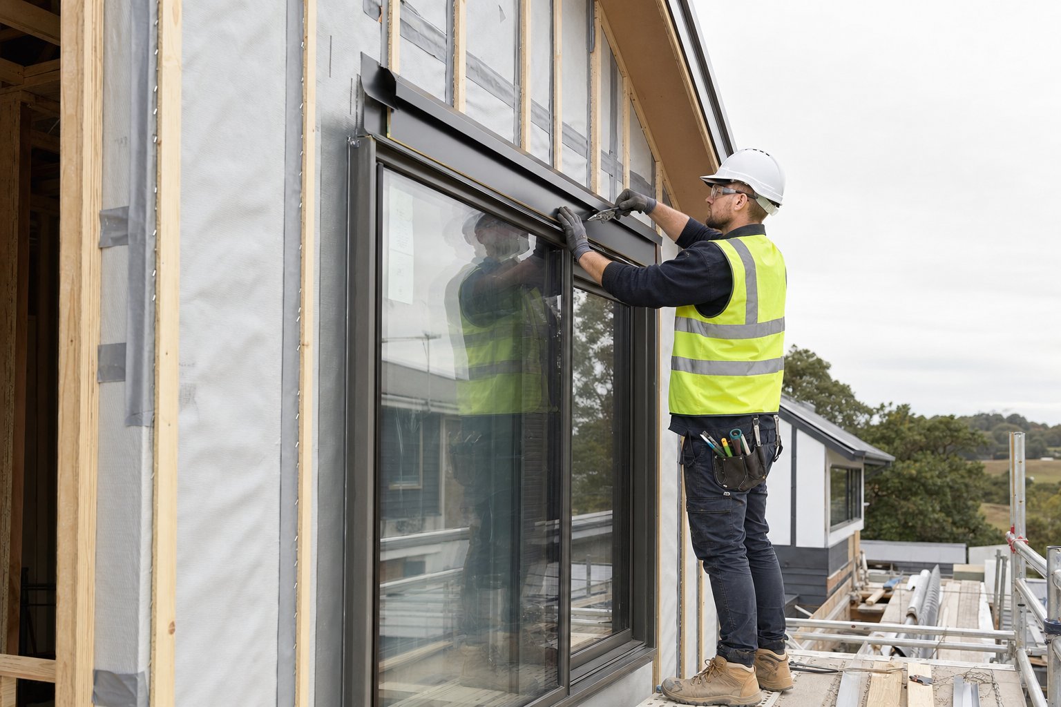
How to Install Aluminium Window Flashing Step by Step
Knowing which profile goes where, which alloy suits the environment, and how cladding systems interact with metal flashing only matters if the installation sequence is correct. A perfectly specified flashing installed in the wrong order — or with the wrong lapping direction — becomes a water collection system rather than a water diversion system. The difference between a watertight window and a leaking one often comes down to which piece went on first.
The logic is straightforward. Water flows downhill. Every upper component must overlap the one below it so gravity carries moisture outward across the surface rather than behind it. This shingle-fashion principle dictates a strict bottom-to-top sequence around the full window perimeter: sill first, then jambs, then head. Reverse any part of that order and you create what building envelope consultants call a reverse lap — the single most common cause of window installation leaks.
Correct Installation Sequence Around the Full Perimeter
Before any flashing is fixed, the rough opening must be clean, dry, and structurally sound. Dust, cobwebs, mortar residue, and moisture on the substrate surface all compromise adhesion of flexible membranes and back-bedding sealant beneath rigid flashings. A quick pass with a stiff brush and a visual check for timber decay takes two minutes and eliminates the most preventable category of installation failure.
The following window flashing installation sequence applies to new construction with aluminium window units set into timber or steel-framed rough openings with a sheet or wrap-type WRB already installed on the wall:
- Prepare the rough opening. Cut the WRB back approximately 50 mm from the rough opening edges on all four sides. This exposes clean substrate for direct membrane adhesion. Fold and secure the cut edges neatly — they will be incorporated in later lapping steps.
- Install the secondary sill membrane. Apply a self-adhered flexible flashing membrane across the rough sill, wrapping upward 100 mm at each jamb and extending outward over the face of the WRB below by at least 75 mm. This creates the secondary drainage tray discussed in the previous section. Roll firmly with a J-roller to eliminate air pockets and ensure full adhesion.
- Set the aluminium sill pan. Position the pre-formed pan over the membrane, confirming the back-slope falls outward at minimum 6 degrees. Fix through the back dam only, using fasteners appropriate to the substrate. Do not fix through the pan base where standing water could accumulate around penetrations.
- Install jamb flashings. Apply flexible membrane strips to both jambs, extending from 50 mm below the sill pan onto the wall below, up to at least 50 mm above the head location. The bottom edge of each jamb membrane laps over the sill membrane already in place. Press firmly into the internal corner at the sill-to-jamb junction.
- Set the window into the opening. Apply a continuous bead of back-bedding sealant to the interior face of the window flange at head and jambs only — not at the sill, where it would block drainage. Position the window, check for level and plumb, shim, and fix per the manufacturer’s instructions.
- Apply jamb cover flashing (if using rigid aluminium angles at jambs). Screw-fix the aluminium jamb profiles over the window flange and the membrane beneath, with the outer leg lapping over the WRB face. Slotted holes at the top fixing point allow vertical thermal movement.
- Install the aluminium head flashing. Position the head drip cap so its upper leg tucks behind the WRB above and its drip edge projects a minimum of 15 mm past the window face. End dams sit over the top of the jamb flashings or jamb cover pieces. Fix through the upper leg into the lintel or header framing.
- Apply the final head membrane tie-in. Bridge a strip of flexible flashing tape from the head flashing upstand onto the WRB above, lapping over the top edges of the jamb membranes. This final piece is the uppermost shingle layer — it ties the entire assembly back into the wall’s drainage plane.
- Fold the WRB over the head tape. The house wrap or WRB sheet above the window folds down over the head membrane, completing the shingle-lap system. Tape or mechanically secure the WRB at this junction.
Each step builds on the one below. If you are learning how to install window flashing for the first time, the mental model is simple: imagine pouring a bucket of water onto the wall above the window. At every single junction, the water should flow over the next surface down without any opportunity to get behind it. If your lapping order achieves that, the sequencing is correct.
Fastener and Sealant Placement Best Practices
Fastener selection depends on exposure. For sheltered inland locations — suburban Melbourne, Canberra, or inland Adelaide — hot-dip galvanised steel screws provide adequate corrosion resistance at a lower cost. Within 1 km of the coastline or in tropical zones north of Bundaberg, stainless steel grade 316 is the minimum. Grade 304 pits in salt-laden environments and should not be used where marine aerosols are present.
Fastener placement follows one rule: never fix through the active drainage surface of any flashing. Screw through the back dam of a sill pan (above anticipated water level), through the upper leg of a head flashing (behind the cladding where water is not flowing), and through the concealed leg of a jamb piece. Every penetration through a flashing surface that carries water is a potential leak point, regardless of how well the screw is sealed.
Sealant placement is where many installations go wrong. Two distinct approaches exist, and confusing them causes failures:
- Back-bedding sealant: Applied behind the flashing or behind the window flange before the component is pressed into position. It fills irregularities in the substrate, creating a compression seal that is protected from UV, weather, and physical damage. Back-bedding is the preferred approach at head flashing upstands, at window flanges against jamb flashings, and between sill pans and their supporting membranes. Use a neutral-cure silicone or polyurethane that remains permanently flexible.
- Face-seal sealant: Applied to exposed joints after installation — visible beads across flashing-to-cladding junctions. Face seals degrade faster because they are exposed to UV, thermal cycling, and physical abrasion. They should be treated as a secondary line of defence, not the primary moisture barrier. Where possible, design the detail to perform without the face seal so that when the sealant eventually fails (and it will), the assembly still sheds water through mechanical overlap alone.
At corners — where jamb membranes meet sill membranes, or where head flashings terminate against end dams — a combination of both approaches works best. Back-bed the aluminium corner joint with sealant, press into position to compress the bead, then apply a patch of flexible membrane over the external face of the corner as a redundant seal. This belt-and-braces method addresses the highest-risk locations without relying on any single material.
Retrofit Flashing Techniques for Existing Windows
Installing window flashing on existing windows presents a different set of constraints. The window is already in place. The cladding is finished. Access to the rough opening is limited to what can be reached by removing trim, cutting back cladding locally, or working from the exterior face. The window flashing how to approach changes from an ideal-sequence exercise to a practical intervention that achieves the best possible result within physical limitations.
Retrofit scenarios typically arise when an older home shows water damage at the sill, when windows are being replaced without full recladding, or when a building assessment identifies missing flashings as a defect. The technique differs from new construction in three key ways:
- Limited lapping access. You cannot always achieve a full shingle-lap behind existing cladding. Instead, a combination of cut-in flashings (slid behind the cladding course above the window) and face-applied kick-out flashings (fixed over the cladding face at the sill) replaces the ideal concealed system.
- Reliance on sealant at transitions. Where the shingle-lap cannot be achieved mechanically, a back-bedded sealant joint between the flashing and the existing cladding or frame becomes the primary moisture barrier at that specific transition. This is not ideal, but it is realistic — and it is vastly better than no flashing at all.
- Working around existing fixings. The window’s mounting screws already penetrate the rough opening framing. Adding a sill pan membrane beneath an existing window frame is only possible if the frame can be temporarily lifted or removed. If it cannot, a face-fixed apron flashing beneath the external sill — lapping over the cladding below — provides the next-best water diversion.
For a head flashing retrofit, the typical approach involves removing a single course of cladding above the window (or lifting a weatherboard), sliding the upper leg of the aluminium drip cap behind the WRB or building paper, and refixing the cladding over it. The cladding conceals the upper leg and restores weather protection. The drip edge projects below, throwing water clear of the frame. This method achieves a genuine shingle-lap at the head without replacing the entire wall cladding — a practical way to address missing head flashings on older Australian homes built before current NCC requirements were common practice.
Regardless of whether the project is new or retrofit, certain mistakes recur across building sites. Recognising them before they happen is faster than fixing them after the cladding goes on:
- Reverse lapping at the head. Tucking the head flashing behind the window flange instead of over it. Water tracks behind the flange and enters the wall.
- Sealing the sill pan drainage edge. Running a continuous sealant bead across the bottom of the window frame, blocking the very path water needs to exit. Leave the front edge open.
- Stretching self-adhered membrane during application. Stretched tape contracts as it relaxes, pulling away from corners and creating gaps at the most critical junction points. Apply with zero tension and use a roller to bond.
- Fixing through the drainage face of the sill pan. Every screw through the pan base is a hole below the waterline. Fix at the back dam or end dams only.
- Omitting the final head membrane tie-in. Installing the rigid head flashing but forgetting to bridge the gap between its upstand and the WRB above. Industry reporting on flashing tape errors identifies this missed step as a primary failure point, because water behind the cladding simply pours down behind the unconnected metal.
- Using incompatible fasteners. Galvanised screws in coastal zones, or steel rivets through aluminium in damp environments, triggering galvanic corrosion at the fastener location — exactly where you need long-term integrity.
The window flashing install process is methodical, not complex. Each step serves the same underlying principle: water over, never behind. Builders who internalise that single rule rarely produce a reverse lap, regardless of whether they are flashing a new opening or retrofitting a detail that should have been there from the start.
Correct installation gets the assembly working on day one. The question that follows is whether it continues working as wall assemblies become more thermally ambitious — deeper insulation layers, outboard-mounted windows, and airtightness targets that leave no tolerance for moisture reaching the interior. High-performance enclosures demand flashing geometries that go beyond standard residential practice.
Specifying Flashing for High-Performance Window Assemblies
Standard residential wall assemblies in Australia — a 90 mm timber frame with brick veneer or direct-fixed cladding — position the window within the structural frame depth. The flashing geometry is relatively simple because the window sits close to the drainage plane. But high-performance enclosures pursuing NatHERS 8-star ratings, Passivhaus certification, or net-zero energy targets change the equation fundamentally. Walls get thicker. Insulation moves outboard. Windows shift position. And the aluminium flashing details that worked on a conventional 230 mm cavity wall no longer reach where they need to go.
Flashing Geometry for High-Performance Wall Assemblies
A split-insulated or externally insulated wall assembly might be 300 mm to 450 mm deep — more than double a conventional frame. Passive House building science recommends positioning the window unit within the insulation layer rather than at the structural frame face, because locating the glazing in the middle of the thermal envelope minimises thermal bridging at the frame-to-wall connection. THERM modelling confirms that windows installed at the structural sheathing plane (the traditional nail-flange position) perform significantly worse than those placed within the insulation zone.
This outward shift creates a practical problem for window installation flashing. The drainage plane — typically at the structural sheathing — is now 100 mm to 200 mm inboard of the window position. Flashing around window openings must bridge that gap, connecting the window frame to the WRB across a much deeper reveal than standard profiles accommodate. Traditional drip caps designed for 20 mm projections cannot reach across a 150 mm insulation layer to connect with the weather-resistive barrier behind.
Several approaches solve this geometry challenge in Australian high-performance builds:
- Extended sill pans with elongated back dams: The aluminium pan extends inward across the full insulation depth, with its back dam rising at the structural sheathing plane where it connects to the WRB. Front drainage still occurs at the window position.
- Outrigger mounting frames or window bucks: High-density EPS or plywood bucks project the rough opening outward to the window plane. The WRB wraps out around the buck, bringing the drainage plane to the window location and allowing standard flashing geometry to work normally.
- Stepped flashing transitions: A two-piece approach where one flashing component connects to the WRB at the sheathing plane, and a second laps over it at the window position. The overlap between pieces must be generous — minimum 75 mm — to prevent wind-driven water from bridging the gap.
High-performance construction detailing shows that when exterior insulation locates the window outboard of the structural frame, the horizontal surface at the header creates a shelf where water can pool. This ledge requires its own waterproofing — a self-adhered membrane dressed over the horizontal surface and lapped into the head flashing above. Without it, water accumulates at the insulation-to-buck junction and eventually migrates inward. The same principle applies to door and window flashing at wider openings, where the horizontal ledge surface is even larger and the pooling risk more acute.
Airtightness demands add another layer. Passivhaus-level targets (below 0.6 ACH at 50 Pa) require a continuous air barrier around every opening. The aluminium flashing itself is not the air barrier — it handles liquid water. A separate air-sealing tape or membrane must connect the window frame to the interior air-control layer, typically running from the frame across the reveal to the internal smart membrane or vapour-control layer. Confusing these two functions — expecting the metal flashing to provide both water management and airtightness — leads to compromised performance in both roles.
Writing Aluminium Flashing Into Project Specifications
Proper window flashing starts on paper, not on site. A specification that simply states “provide aluminium flashing at all window openings” leaves every critical decision to the installer’s discretion — alloy, thickness, finish, fixing method, and dimensional standards become a gamble. For projects targeting above-code performance, the specification must be explicit enough that the fabricator and installer cannot deviate without raising a question.
A complete aluminium flashing specification should address each of the following items:
- Alloy and temper: Nominate specifically (e.g., 5005-H32 for coastal, 3003-H32 for inland). Do not specify “aluminium” generically.
- Thickness: State minimum gauge for each location — 0.7 mm for residential head and sill; 1.2 mm minimum for commercial or exposed applications.
- Finish: Specify mill, anodised (state micron thickness), polyester powder coat (state colour system), or PVDF. Include the RAL or Colorbond colour code where relevant.
- Profile geometry: Reference project drawings for exact dimensions — upstand heights, drip projections, end-dam heights, slope angles. Do not leave these to the fabricator’s “standard” profile.
- Fixing method: Nominate fastener type (stainless steel grade 316, galvanised), head style (hex washer, countersunk), and fixing centres. Specify slotted holes for thermal movement where lengths exceed 1,200 mm.
- Sealant type: Call out compatible sealant chemistry — neutral-cure silicone or polyurethane for back-bedding; butyl tape for expansion joints. Prohibit acetic-cure products against aluminium.
- Applicable standard: Reference AS 2904 for damp-proofing and flashing requirements in Australia. For international projects, reference EN 14783 (Europe) or ASTM B209 (North America) as applicable.
- Isolation requirements: Specify where dissimilar-metal isolation is required, including the type of isolator (neoprene, EPDM, polyethylene tape) and where alkaline substrate protection applies.
Aluminium windows installation specifications should cross-reference the flashing schedule, ensuring the window supplier and the flashing fabricator work from the same dimensional data. When the window frame depth, flange width, and mounting position are confirmed, the flashing dimensions follow directly. A 50 mm window flange requires a different head flashing downturn than a 30 mm flange. If these are specified independently by different consultants without coordination, clashes on site are inevitable.
Key takeaway: Window selection and flashing design are not independent decisions. The window frame profile, its mounting position in the wall, and the flashing geometry around it form a single integrated system. Specify them together from the outset, or accept that site improvisation will fill the gaps your documentation left open.
Choosing Window Systems Designed for Proper Flashing Integration
The most detailed specification still relies on the window product being compatible with proper flashing at every perimeter location. Thermally broken aluminium frames — the standard for high-performance Australian builds — feature complex profile geometries with multiple chambers, thermal isolators, and drainage channels built into the frame. These profiles interact directly with the flashing around window openings, and not all frame designs accommodate field-installed flashings equally well.
Features to look for in a window system that supports robust flashing integration include:
- Clearly defined drainage channels at the sill that align with external pan flashing outlets
- Sufficient flange width to permit back-bedded sealant plus mechanical overlap with the head drip cap
- Frame profiles that accept standard flashing at window positions without requiring custom-bent profiles for every project
- Documented installation details showing how the manufacturer’s frame interfaces with typical WRB and flashing configurations
- Custom sizing options that match specific rough opening dimensions, minimising the gap between frame and structure where flashing must bridge
Manufacturers who provide detailed flashing integration guidance alongside their window products simplify the coordination challenge considerably. MEICHEN’s aluminium window systems, for example, offer Australian homeowners, builders, and architects a range of window types with custom options and performance considerations aligned to project-ready specification. Their product documentation addresses how frame profiles interface with field-installed flashings — the kind of manufacturer-level coordination that prevents the responsibility gaps discussed earlier in this guide.
Whether pursuing a 7-star NatHERS rating on a suburban renovation or targeting Passivhaus certification on a new build, the principle holds: select the window system and design the flashing assembly as a coordinated package. Treating them as separate procurement items — window from one supplier, flashing from another, with no shared dimensional reference — is how the gap between “designed” and “built” opens wide enough for water to find its way through.
With specification and product selection aligned, the final step is consolidating every dimensional requirement — head, sill, jamb, and corner — into a single reference that serves as the definitive coordination document between designer, fabricator, and installer.

Complete Flashing Specification Reference and Next Steps
A specification scattered across eight separate detail drawings, three different consultant reports, and a manufacturer’s generic installation sheet is a specification that gets misread on site. The entire purpose of consolidating window flashing details into a single reference is coordination — giving the fabricator, installer, and certifier one document where every dimension, every overlap, and every lapping direction is resolved before metal is cut.
So what does window flashing look like when every perimeter location is drawn together as an integrated system? It looks like a continuous chain of overlapping components, each one handing water to the next in an unbroken sequence from head to sill. No single piece works alone. The head drip cap means nothing without the jamb membrane beneath it to catch what rolls off the ends. The sill pan achieves nothing without a clear drainage path forward and a WRB connection below. Understanding why each dimension exists — the physics behind the numbers — is what separates a builder who installs flashing correctly from one who merely installs flashing.
Integrated Flashing Diagram for All Four Perimeter Locations
A window flashing diagram that covers the full perimeter reveals a hierarchy governed by gravity, surface tension, and wind pressure. Each location faces a different dominant force, and the dimensions at that location exist to defeat that specific force.
Head: The dominant force is gravity — water running down the wall face from above. The upstand height (minimum 50 mm) exists because water splashes upward 30 mm to 40 mm when it strikes a horizontal surface. The drip projection (minimum 15 mm) exists because surface tension holds water against the underside of horizontal metal. The outward slope (minimum 15 degrees) exists because standing water on a flat surface builds hydrostatic pressure against lap joints. Every dimension at the head addresses a specific mechanism that would otherwise allow water past the flashing line.
Sill: The dominant forces are gravity and hydrostatic pressure — water accumulates rather than flows past. The back-slope (minimum 6 degrees) prevents ponding. End-dam heights (minimum 25 mm residential, 40 mm high-exposure) contain lateral migration driven by wind pressure on the collected water film. The front drainage gap (minimum 50 mm unsealed) allows evacuation under gravity alone. Every dimension at the sill addresses the fact that this location collects rather than deflects — it is a reservoir that must empty faster than it fills.
Jambs: The dominant forces are wind pressure and capillary action — lateral movement along horizontal surfaces and upward wicking through narrow gaps. Overlap dimensions (minimum 50 mm over WRB) ensure that wind-driven water cannot travel the full overlap distance before gravity redirects it. The turned edge or membrane wrap (minimum 100 mm return into the opening) blocks capillary paths at the frame-to-structure junction. Every dimension at the jamb addresses the horizontal and upward forces that gravity alone cannot defeat.
Corners: Corners are where two flashing planes meet — head-to-jamb and sill-to-jamb. The dominant force is capillary action concentrated into the internal angle. Water drawn into a tight corner develops higher capillary pressure than on a flat surface because the gap narrows. Folded corners (not cut-and-sealed) eliminate the gap entirely. Where folded construction is impractical, a minimum 75 mm membrane patch over the external face of the corner joint blocks capillary pathways. Every detail at a corner addresses the convergence of forces that makes junctions the weakest link in any window flashings assembly.
Viewed as a complete exterior window flashing diagram, the system reads as a watershed — an engineered topography where every surface slopes outward, every junction shingle-laps downward, and every termination includes a dam or seal that prevents lateral escape. The dimensional table below consolidates every critical measurement into a single reference, cross-referenced to the standards that govern minimum compliance.
Complete Dimensional Specification Reference Table
The following table draws together the minimum dimensions for flashing around windows at every perimeter location. These figures represent the baseline for compliant installation. Project-specific conditions — higher wind zones, greater wall catchment area, deeper insulation cavities, or coastal salt exposure — may justify increasing these minimums. Where local standards specify different values, the more stringent requirement governs.
| Location | Minimum Upstand | Minimum Overlap | End Dam Height | Drip Projection | Applicable Standard |
|---|---|---|---|---|---|
| Head | 50 mm (60 mm in extra-high wind zones with hooked edge) | 50 mm of upstand behind WRB; cladding covers minimum 35 mm of upstand | 10–25 mm turn-ups at each end (match upstand or local water volume) | 15–20 mm beyond window face (formed kick at 45 degrees) | AS 2904; IRC R703.4.1; EN 14783 |
| Sill | 25–40 mm back dam above pan base | 50 mm front edge over WRB below opening | 25 mm residential; 40–50 mm high-exposure or high-catchment | N/A — front edge laps over WRB rather than projecting as drip | AS 2904; IRC R703.4.1; EN 14783 |
| Jamb | Membrane return minimum 100 mm into rough opening | 50 mm over face of WRB at jamb; extends 50 mm above head and below sill locations | N/A — jamb flashings are continuous vertical strips, not dammed | N/A — drainage occurs downward along the vertical membrane face | AS 2904; IRC R703.4.1; EN 14783 |
| Corner (Head-to-Jamb) | Head flashing end dam sits over top of jamb membrane | 75 mm membrane patch over external corner junction; head drip extends 20 mm past jamb line | End dam height matches head flashing upstand (minimum 10 mm) | Head drip edge projects past jamb scriber by minimum 20 mm | AS 2904; IRC R703.4.1; EN 14783 |
| Corner (Sill-to-Jamb) | Sill pan end dam rises to full end-dam height (25–50 mm) | Jamb membrane overlaps sill membrane by minimum 50 mm; pressed firmly into internal angle | Sill end-dam height as per sill row above | N/A — drainage exits at the sill front edge, not at the corner | AS 2904; IRC R703.4.1; EN 14783 |
The 2024 International Residential Code (IRC) Section R703.4 requires that approved corrosion-resistant flashing be applied in a manner that prevents entry of water into the wall cavity, with overlapped flashing applied in shingle fashion. It mandates flashing at exterior window and door openings specifically under R703.4.1. Australian projects reference AS 2904 for damp-proofing and flashing in buildings, which establishes equivalent performance requirements adapted to local climate zones and construction methods. European standards under EN 14783 cover self-supporting metal sheet for roofing, external cladding, and internal lining, including flashing components.
These standards converge on the same physics-based principles: flashing must intercept moisture, maintain drainage continuity, and integrate with the weather-resistive barrier without creating reverse laps. The dimensional specifics vary by jurisdiction and exposure condition, but the underlying logic is universal — gravity moves water downward, wind pressure drives it laterally, capillary action draws it into tight gaps, and surface tension holds it against smooth surfaces. Every number in the table above exists to overcome one of these four forces at the specific location where that force dominates.
Coordinating Window Selection with Flashing Design
The reference table resolves the dimensions. The specification resolves the materials. But none of it matters if the window product itself cannot accommodate those flashings at the frame interface. A head flashing requiring a 50 mm upstand tucked behind the WRB means nothing if the window’s top flange is only 20 mm wide and the drip cap cannot achieve proper overlap at the downturn. The window frame profile and the flashing geometry must be confirmed as compatible before either is ordered.
This coordination challenge is why specifiers increasingly look for window manufacturers who document their frame-to-flashing interfaces explicitly — not as an afterthought in a generic installation guide, but as part of the project documentation that fabricators and installers actually use. When flashing dimensions are designed around a specific window frame profile, the gap between design intent and site execution narrows considerably.
For Australian residential and commercial projects, selecting aluminium windows from manufacturers who provide detailed flashing integration guidance simplifies the coordination between window frame profiles and field-installed flashings. MEICHEN’s range of aluminium window systems demonstrates this approach — offering custom options, multiple window types, and performance considerations that align with specification-ready project integration. Their product page serves as a practical next step for readers looking to understand how specific frame profiles interface with the window flashing details covered throughout this guide.
Whether the project is a single-storey renovation in suburban Adelaide or a multi-storey commercial build on the Gold Coast, the principle remains constant: the window and its flashing are a single coordinated assembly. Specify them together. Procure them with shared dimensional references. Install them in the correct sequence. And verify every lap direction before the cladding conceals the evidence of what was — or was not — done right.
Frequently Asked Questions About Aluminium Window Flashing Details
1. What is the correct installation order for aluminium window flashing?
The correct sequence follows a strict bottom-to-top approach: install the sill pan flashing first, then the jamb flashings, and finally the head flashing. This order ensures every upper component overlaps the one below it in shingle fashion, so gravity carries water outward across each surface rather than behind it. Reversing any part of this sequence creates a reverse lap — one of the most common causes of window leaks identified in building envelope investigations across Australia.
2. Why do window sills fail before other flashing locations?
Sills collect all the water that the rest of the window assembly cannot fully divert — including moisture breaching the primary frame seal, condensation draining down the glass interior, and wind-driven spray bypassing head and jamb flashings. Unlike the head, which deflects water, the sill must collect, contain, and evacuate moisture before it reaches the rough opening timber. Forensic investigations consistently rank improper sill flashing as the number one source of window leaks in Australian homes, ahead of head flashings, jamb failures, and sealant breakdown combined.
3. What aluminium alloy should I use for window flashing in coastal Australia?
For coastal environments within salt-air zones, alloy 5005-H32 is the recommended choice. Its magnesium content delivers superior corrosion resistance compared to the standard 3003 alloy used in inland suburban builds. Alloy 5005 also produces a smooth, uniform surface when anodised, making it ideal for architecturally exposed flashings that remain visible on the finished elevation. For marine-grade commercial applications, alloy 5052-H32 offers the highest corrosion performance in the 5xxx series, though it is less formable for complex profile bends.
4. How do I prevent galvanic corrosion when aluminium flashing contacts other metals?
Galvanic corrosion occurs when aluminium touches a more noble metal in the presence of moisture — common pairings on Australian building sites include aluminium flashing against copper downpipes, uncoated steel lintels, or zinc cladding. Isolation methods include neoprene or EPDM pads between contact surfaces, polyethylene or bituminous tape at bracket-to-flashing junctions, EPDM washers beneath stainless steel screw heads, and aluminium rivets where structural loads are minimal. The barrier must be continuous at every contact point to be effective.
5. Can aluminium window flashing be retrofitted to existing windows?
Yes, retrofit flashing is both practical and significantly better than leaving windows unflashed. The technique differs from new construction because access to the rough opening is limited. At the head, a drip cap can typically be slid behind the cladding course above the window by removing a single board or lifting a weatherboard. At the sill, a face-fixed aluminium apron flashing lapping over the cladding below provides effective water diversion when a concealed pan is impractical. Sealant at transitions replaces the full shingle-lap where mechanical overlap cannot be achieved, and the existing rough sill must be checked for decay before any new flashing is installed.
More Window & Door Guides