What Are Aluminium Window Fixing Details and Why They Matter
Every aluminium window starts life as a precision-engineered product. But the moment it leaves the factory, it faces an unpredictable reality: the building it needs to connect to. Aluminium window fixing details are the technical specifications that define exactly how a window frame anchors into a structural opening, covering bracket types, fastener positions, embedment depths, sealant lines, and load paths from frame to substrate. They are not generic install instructions. They are site-specific engineering documents that account for the wall material, exposure conditions, and forces acting on that particular opening.
What Aluminium Window Fixing Details Actually Describe
Think of fixing details as the translation layer between a manufactured aluminium profile and a unique building structure. A correct window installation depends on resolving the interface between two very different things: a factory-produced frame with tight tolerances, and a site-built wall that varies in material, flatness, and structural capacity. The fixing detail bridges that gap by specifying:
- The type and position of mechanical fixings (screws, anchors, brackets, or cleats)
- Minimum embedment depths and maximum fixing centres for the given substrate
- Shimming and packing requirements to achieve plumb, level, and square alignment
- Sealant and membrane sequencing for weatherproofing at every penetration point
- Clearance gaps and compressible fillers that accommodate structural movement
Without these specifications, an aluminium window installation becomes guesswork. The installer might use the right screws for a concrete reveal but the wrong ones entirely for an AAC block wall. A fixing schedule designed for a sheltered single-storey home will fail on an exposed coastal facade in northern Queensland. The detail itself is what ties every decision together into a coordinated system.
Why Fixing Details Determine Installation Success or Failure
At every fixing point, loads transfer from the window frame into the surrounding structure. Wind pressure pushes inward. Suction pulls outward. The dead weight of the glazed unit bears down on the sill fixings. Operable sashes generate lateral and lever-arm forces at hinges and tracks each time someone opens or closes them. These forces must travel a clear, uninterrupted path from the aluminium profile, through the fastener, and into solid substrate material capable of resisting them.
Fixing details are the engineering bridge between a manufactured window product and a unique building structure. Get them wrong, and no amount of quality in the frame or glass will prevent leaks, movement, or failure.
This is precisely why generic aluminium window installation guides fall short. They might tell you to fix at 150 mm from each corner and at 600 mm centres along the jamb, but they rarely address what happens when the substrate is lightweight block instead of solid brick, or when the opening sits in a high wind zone rated under AS 2047. The substrate type changes the anchor selection. The exposure category changes the fixing spacing. The window type changes where operational loads concentrate.
Thermal performance adds another layer. Every fixing bracket or screw that bridges the insulation zone creates a potential thermal bridge, a cold spot where condensation can form and energy escapes. Poorly resolved fixing details compromise the very thermal break technology built into modern aluminium profiles.
This guide breaks down the complete anatomy of aluminium window fixing details as they apply across Australian construction types, from brick veneer and timber framing to concrete and steel. Regardless of which aluminium system or brand you are working with, the principles of correct window installation remain consistent. The substrate, the exposure, and the window type dictate the fixing approach, and the detail document is where all three converge into a buildable solution.
Frame-to-Wall Junction Anatomy Explained Layer by Layer
A single cross-section through the frame-to-wall junction reveals just how many components must work together in a coordinated sequence. Each layer has a distinct job, and the order matters. Skip one, reverse two, or leave a gap unsealed, and water finds a path. Understanding this anatomy is the foundation for fitting aluminium windows correctly in any Australian wall type, whether brick veneer in Melbourne or rendered block in Brisbane.
Cross-Section Anatomy from Interior to Exterior
Picture slicing horizontally through a jamb where the aluminium frame meets the structural reveal. Moving from inside the room outward, here is what a properly detailed junction contains:
- Interior plaster or lining — The visible finish (plasterboard, timber reveal liner, or render) that conceals the junction and provides the interior air seal boundary.
- Low-expansion foam or backer rod and sealant — Fills the gap between the lining and the frame, completing the interior air and thermal barrier without exerting pressure on the profile.
- Packing and shimming zone — Composite or plastic shims placed at fixing points to achieve plumb, level, and square alignment. These transfer dead load and operational forces directly into the structure behind.
- Fixing bracket or direct-fix screw — The mechanical connection itself, whether a lug cleat anchored into the reveal or a screw driven through the frame profile into substrate material.
- DPC (damp proof course) membrane — A flexible membrane wrapped around the reveal face to prevent moisture migration from masonry into the frame zone. Critical in brick veneer and rendered masonry construction.
- Primary sealant line — A continuous bead of exterior-grade sealant (typically polyurethane or neutral-cure silicone) bridging the aluminium frame to the wall substrate, forming the weather seal.
- Aluminium frame profile — The window fin detail or face of the outer frame, often incorporating a rebate or channel that receives the sealant and directs water outward.
- Exterior weather seal and drainage gap — An air gap or drained cavity that allows any water penetrating the outer cladding to fall harmlessly down the drainage plane rather than pooling against the frame.
- External cladding or render — The outermost visible layer (brick, render, weatherboard, or panel cladding) that terminates at the window edge with appropriate clearance and flashing.
The drainage path concept is central to this assembly. Water management in any window opening relies on gravity and pressure equalisation. A sliding frame in a window assembly or a fixed panel alike must allow any moisture that breaches the outer seal to drain downward and exit at the sill, never pooling against the frame or backing into the wall cavity. This is why the sill junction typically remains unsealed at its outer edge, providing a deliberate escape route.
The Role of Shims, Packers, and DPC in Frame Alignment
Shims do more than level a frame. They are structural transfer points. Every fixing screw should pass through a shim so that clamping force bears on a solid packer rather than deflecting the aluminium profile. Paired shims, one from each side, create a flat bearing surface regardless of the gap width. Composite shims are the preferred choice in Australian conditions because they resist moisture absorption and dimensional change over time.
The DPC membrane wraps around the inner face of the reveal before the frame goes in, lapping down over any mortar joints or raw masonry. Its purpose is straightforward: stop rising or lateral damp from reaching the frame zone where it could degrade fixings or cause internal condensation. In timber-framed walls, a flexible flashing tape typically replaces the traditional DPC, performing the same moisture separation role while also acting as a secondary air barrier.
Together, these layers form a system where each component relies on the next. The interior seal stops conditioned air leaking out. The shims hold geometry under load. The fixings anchor everything to structure. The DPC blocks moisture migration. The exterior sealant sheds bulk water. And the drainage gap ensures that whatever gets past the outer defences has somewhere to go besides deeper into the wall. Knowing where each bracket type sits within this layered assembly is what separates a coordinated fixing detail from a loose collection of materials bolted together on site.
Fixing Bracket Types and When to Use Each Method
Where a bracket sits within that layered junction dictates how loads transfer, how much adjustment is possible on site, and whether the weatherproofing sequence can be maintained without compromise. Four primary fixing methods dominate aluminium window installations across Australian construction, and choosing the wrong one for your substrate or opening size is where problems begin.
Direct Fix Through Frame Method
Direct fix is the most straightforward approach. A screw passes through a pre-drilled hole in the aluminium frame profile, through any packing, and directly into the structural substrate behind. It works well on solid masonry reveals, concrete, and timber studs where the frame sits tight to the structure with minimal gap. The method delivers a clean, compact junction because no additional bracket protrudes from the frame back.
The trade-off is limited adjustment. Once the screw compresses the frame against its packers, you cannot shift the frame laterally without pulling fasteners and re-drilling. Direct fix also requires careful attention to thermal bridging because the metal screw creates a conductive path straight through the insulation zone. In direct fix cladding systems, where the window frame is fixed directly onto framing members without a cavity, the cladding then overlaps the outer face of the joinery to create a sealed appearance. This approach suits moderate openings in sheltered to semi-exposed locations where fine adjustment is less critical than simplicity and speed.
Lug and Cleat Bracket Systems
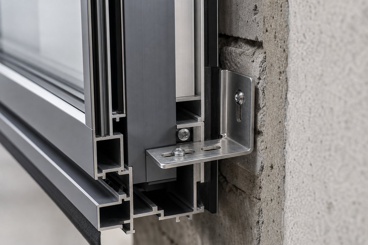
Lugs (also called cleats) are L-shaped metal brackets screwed to the back of the aluminium frame and then anchored into the reveal face with separate fasteners. The frame floats independently of the wall surface, connected only at discrete bracket points. This separation gives installers significant adjustment capacity in three axes — the frame can be shimmed, shifted, and squared before the bracket is finally anchored home.
Lug systems are the default choice for larger openings, higher wind zones, and situations where the reveal surface is uneven or the gap between frame and structure exceeds what a direct-fix screw can span. They also reduce thermal bridging compared to through-frame screws because the bracket can incorporate a thermal isolator or sit behind the insulation line. Most commercial aluminium installations in Australia use lug and cleat fixings as standard, particularly for openings above 1200 mm in any dimension or in wind classifications above N2.
Sub-Frames and Nail Fin Applications
A sub-frame is a secondary frame, typically aluminium or galvanised steel, fixed to the structural opening first. The window unit then clips or screws into the sub-frame. This two-stage approach decouples the window from the structure, making future replacement straightforward and allowing the builder to prepare and waterproof the opening well before the glazing arrives on site. Sub-frame installations are common in commercial projects, high-rise residential, and renovations where preserving existing interior finishes matters. The visible glass area may reduce slightly because the sub-frame occupies space within the rough opening, but the trade-off is superior adjustability and a cleaner sequencing of trades.
Nail fin systems take a different path entirely. An integrated flange extends from the outer edge of the aluminium frame, and this fin is nailed or screwed directly to timber or light-gauge steel framing before the exterior cladding goes on. Installing nail fin windows is the standard method in timber-framed construction across much of Australia, particularly in residential builds where weatherboard, fibre cement, or sheet cladding wraps over the fin to create a lapped weather seal. The nail fin window installation process is fast, provides inherent weatherproofing when correctly taped and flashed, and eliminates the need for separate brackets. However, installing a window with a nailing fin requires access to the framing face before cladding, making it unsuitable for retrofit situations where the exterior skin is already in place.
| Fixing Method | Best Substrate Match | Max Opening Suitability | Wind Load Capacity | Ease of Adjustment |
|---|---|---|---|---|
| Direct fix through frame | Solid masonry, concrete, timber studs | Small to medium (up to ~1500 mm) | Moderate | Low — limited once fastened |
| Lug and cleat brackets | All substrates including lightweight block | Medium to large (1200 mm+) | High | High — adjustable in three axes |
| Sub-frame (retrofit frame) | Concrete, masonry, existing openings | Large openings, multi-panel assemblies | High (dependent on sub-frame design) | Very high — window clips into pre-set frame |
| Nail fin (integrated flange) | Timber frame, light-gauge steel frame | Standard residential sizes | Moderate to high (when properly flashed) | Very low — fixed before cladding |
Selecting the right method is never purely about preference. The wall substrate determines which anchors will hold. The opening size and wind classification determine how many fixings are needed and how much pull-out strength each must provide. And the construction sequence, whether the cladding is already on or yet to be installed, determines whether a nail fin is even an option. These substrate-specific demands are where the next layer of detail sits, and where generic guidance most often fails Australian builders working across varied construction types.
Wall Substrate Fixing Methods from Concrete to Timber
The bracket type only tells half the story. A lug cleat bolted into solid reinforced concrete behaves completely differently from the same bracket anchored into an AAC block, even if the screw diameter looks identical on paper. The substrate — the actual material receiving the fastener — governs pull-out resistance, embedment depth, fixing centres, and anchor selection. Get this wrong and you fit aluminium windows that feel solid on day one but loosen under wind cycling or crumble at the anchor point within a few seasons.
Australian residential and commercial construction uses a wide mix of wall substrates, often within a single project. A brick veneer home in Sydney might present solid clay brick at the external leaf, a timber stud frame behind, and a concrete lintel above. Each material demands its own fastener strategy. Here is how the fixing specification shifts across the substrates most commonly encountered on Australian sites.
Fixing Into Concrete and Masonry Substrates
Reinforced concrete (RCC) is the most predictable substrate for aluminium window fixings. Its compressive strength is high, its density is consistent, and it accepts mechanical expansion anchors reliably. Sleeve anchors in the 8 mm to 12 mm diameter range are the standard choice for window fixing into concrete reveals and slab edges. These expand radially when tightened, gripping the walls of the drilled hole with substantial pull-out resistance.
For heavily loaded openings or situations where vibration might loosen a mechanical anchor over time, chemical anchors (two-part resin capsules injected into a drilled hole before inserting a threaded rod) provide superior performance. Chemical anchors bond to the concrete at a molecular level, distributing load across the full embedment length rather than relying on friction at the expansion point alone. They are particularly useful where fixings fall close to a concrete edge, since they generate far less splitting force than expansion-type fasteners.
Minimum embedment into solid concrete is typically 50 mm for window frame fixings under standard load conditions, though this increases with wind classification and opening size. Maximum fixing centres for concrete substrates generally sit at 600 mm along the frame length, reducing to 450 mm or less in higher wind zones.
Solid clay brick masonry is similarly reliable but introduces one critical variable: mortar joints. Fixing into the brick unit itself gives consistent strength, while fixing into the mortar bed or perpend joint gives considerably less pull-out capacity. Best practice is to position fixings within the body of the brick, avoiding the mortar line where possible. Where this is not achievable due to frame geometry, longer fixings with deeper embedment compensate for the weaker substrate. Frame fixings designed for masonry — typically a sleeve anchor with a countersunk head or a dedicated frame bolt — are the preferred fastener type, with diameters from 7.5 mm to 10 mm and embedment depths of 50 mm to 60 mm into the brick body.
Timber Frame and Steel Frame Fixing Requirements
Timber-framed walls are widespread across Australian residential construction, from older weatherboard homes in Victoria to modern lightweight builds in Queensland. The window nail fin installation method suits new timber-frame builds perfectly. The integrated flange nails or screws directly into the face of the stud or jack stud through a pre-punched pattern, creating a secure connection before the cladding is applied.
Where a nailing fin window installation is not suitable — in retrofit situations, for example, or where the frame profile does not incorporate a fin — lug brackets or direct-fix screws anchor into the timber studs instead. Coach screws (hex-head lag screws) in 10 mm to 12 mm diameter provide excellent holding power in seasoned softwood framing, with a minimum penetration of 40 mm into solid timber. Standard fixing centres of 450 mm to 600 mm apply, with additional fixings at each corner within 150 mm of frame ends.
The key consideration in timber framing is ensuring the fastener hits solid stud material, not just the lining or nogging. If the rough opening has been trimmed with single studs, the available fixing area is limited to the stud face width — typically 35 mm to 45 mm for standard 90 mm framing. Double-check stud positions before drilling.
Steel-framed construction, increasingly common in multi-storey residential and commercial Australian projects, requires a completely different fastener: self-drilling tek screws. These cut their own thread into the steel member without pre-drilling, creating a secure metal-to-metal connection. For light-gauge steel framing (1.2 mm to 2.4 mm BMT), a No. 10 or No. 12 tek screw with a minimum of three full threads engaged in the steel provides reliable pull-out strength. Heavier structural steel (above 3 mm thickness) may require a No. 14 self-drilling fastener or a bolted cleat connection.
Fixing centres on steel frames mirror timber at 450 mm to 600 mm, but the critical detail is ensuring screws engage the steel member and not just the plasterboard track or lightweight channel behind. Where aluminium frames connect to steel mullion systems in curtain wall applications, mechanical cleat connections using bolted angle cleats transfer loads directly between the window sub-frame and the primary structural steelwork.
Lightweight Block and AAC Anchor Considerations
Autoclaved aerated concrete (AAC) blocks — marketed in Australia under brands like Hebel — present a specific challenge. The material is light, easy to work, and provides good thermal performance, but its low density means standard expansion anchors can pull straight through under load. AAC has roughly one-quarter the compressive strength of standard concrete, so embedment depths and anchor types must be adjusted accordingly.
Specialist AAC anchors feature wider expansion zones or longer threaded profiles that distribute clamping force across a greater area of the soft block material. Nylon frame plugs designed specifically for aerated concrete, paired with appropriate screws, are one common solution. Chemical resin anchors with perforated sleeves offer higher load capacity for heavier window assemblies — the resin fills the porous structure of the AAC, creating a bonded mass around the threaded rod that resists pull-out far better than friction alone.
Minimum embedment depths in AAC should be at least 75 mm to 80 mm, substantially deeper than what solid concrete requires. Fixing centres also tighten: 400 mm maximum is a typical guideline for AAC substrates, with closer spacing in exposed or high-wind locations. Every fixing point must include a packer behind the frame to spread bearing load and prevent the aluminium from crushing into the soft block face under fastener pressure.
| Wall Substrate | Recommended Anchor Type | Screw/Bolt Diameter | Minimum Embedment Depth | Maximum Fixing Centres |
|---|---|---|---|---|
| Reinforced concrete (RCC) | Sleeve anchor or chemical anchor | 8 mm – 12 mm | 50 mm | 600 mm |
| Solid clay brick | Frame bolt or sleeve anchor (into brick body) | 7.5 mm – 10 mm | 50 mm – 60 mm | 600 mm |
| AAC / lightweight block | Specialist AAC nylon plug or chemical anchor with perforated sleeve | 8 mm – 10 mm | 75 mm – 80 mm | 400 mm |
| Timber frame (stud) | Coach screw, nail fin, or Type 17 screw | 10 mm – 12 mm | 40 mm into solid timber | 450 mm – 600 mm |
| Light-gauge steel frame | Self-drilling tek screw (min. 3 threads engaged) | No. 10 – No. 14 (4.8 mm – 6.3 mm) | Full steel thickness + 3 threads | 450 mm – 600 mm |
| Structural steel / curtain wall | Bolted cleat or mechanical bracket connection | M8 – M12 bolt | Per engineered connection design | Per structural engineer specification |
This table provides a starting framework, but project-specific conditions always override generic guidance. Wind classification under AS 2047, proximity to coastal salt air, opening dimensions, and window operational type all influence whether you tighten fixing centres, increase embedment, or upgrade anchor grade. The substrate tells you what will hold — the exposure and load conditions tell you how much holding power you actually need. That relationship between fixing position and the forces acting at each location is where sill, jamb, and head details each tell a different story.
How Sill, Jamb, and Head Fixings Differ in Practice
A fixing point at the sill carries different responsibilities from one at the head or jamb, even when the same substrate sits behind all three. Gravity, water, structural movement, and operational forces each concentrate at different positions around the frame perimeter. Treating all four sides identically is one of the most common shortcuts that leads to leaks, binding hardware, or cracked sealant joints within the first few years of service. Each position demands its own logic.
Sill Fixing Details and Drainage Requirements
The sill is where water collects, which makes it the most failure-prone zone in any window opening. Every fixing penetration at sill level is a potential leak path, so the number and placement of fasteners here must balance structural need against waterproofing integrity. In many aluminium window fixing details, sill fixings are deliberately minimised or offset away from the drainage zone to preserve the weatherproofing membrane beneath the frame.
Effective sill design relies on a pan flashing or sub-sill membrane that catches any water bypassing the outer weather seal and redirects it back outside. Building Science Corporation identifies four essential characteristics of pan flashing: a continuous waterproof surface without holes or wrinkles, a back dam or positive slope directing water outward, end dams at each side preventing lateral water migration into the wall, and lapping over the drainage plane beneath the opening. Any fastener that punctures this membrane without being sealed compromises the entire system.
Key sill fixing principles for leak-free aluminium window installations:
- Drainage slope — The sill substrate must fall toward the exterior at a minimum slope (typically 5 to 10 degrees) so water never pools beneath the frame. Where the structural sill is level, a packer or wedge creates the fall before the frame is set.
- End dams — Upturned edges at each end of the pan flashing prevent water from running sideways off the sill membrane and into the surrounding wall cavity. Corners between end dams and back dams should be folded, not cut, to avoid weak points.
- Sill-to-frame junction sealing — The jambs and head are sealed to the wall with sealant or membrane, but the outer sill edge remains open to allow drainage. Sealing the bottom of the frame to the pan flashing traps water inside the opening rather than letting it escape.
- Fixing penetration management — Where sill fixings are unavoidable (for dead load bearing or to prevent lateral movement), they should sit above the drainage channel line and be sealed with a compatible sealant cap. Some systems avoid sill fixings entirely, relying on the frame weight bearing on packers while jamb and head fixings resist wind loads.
- Shim placement for drainage clearance — Shims at the sill should allow a drainage gap beneath the frame profile, preventing the aluminium from sitting directly on the membrane and blocking water flow.
In concrete slab construction common to Australian apartments and townhouses, a recessed seat cast into the slab edge can serve as an inherent pan flashing with built-in back and end dams. This eliminates the need for separate membrane installation at the sill, provided the concrete surface is smooth and the window frame sits proud of the inner edge.
Head Fixing with Lintel Deflection Allowance
The head of a window opening is where structural movement is most pronounced. Lintels deflect under load. Timber frames shrink as moisture content drops. Concrete beams creep over time. If the window frame is fixed rigidly to the head with zero clearance, any downward movement of the lintel bears directly onto the aluminium profile, distorting the frame, binding operable sashes, and cracking the sealant joint.
The standard engineering response is a head clearance gap: a deliberate space between the top of the aluminium frame and the underside of the lintel or head structure, filled with a compressible material rather than a rigid fixing. This gap accommodates deflection without transmitting load into the window. The industry-standard deflection limit for structural lintels is span divided by 360. For a 2400 mm opening, that translates to roughly 6.5 mm of potential vertical movement under full load — more than enough to crush a sealant bead or jam a casement sash if no gap exists.
Head fixing requirements differ from jamb fixings in several ways:
- Compressible filler — The head gap (typically 5 mm to 10 mm depending on span and lintel type) is packed with closed-cell foam backer rod or a compressible polyethylene strip. This fills the void for insulation and fire-stopping purposes while still yielding under deflection loads.
- Slotted or flexible fixing connections — Where head fixings are required, some aluminium window systems use slotted holes in the head bracket that allow the lintel to deflect without dragging the frame downward. The screw passes through a vertically elongated slot, permitting controlled movement.
- Sealant flexibility — The exterior weather seal at the head must be a high-movement sealant capable of accommodating joint width changes without splitting. Low-modulus silicone or polyurethane sealants rated for at least 25% movement are standard here.
- No rigid packing at head — Unlike sill and jamb positions where solid packers transfer load, head packers should never be load-bearing. They hold the frame in position during installation only and are not intended to resist downward structural movement.
For sliding windows installation where the head track supports the weight of operable panels, the head fixing detail becomes even more critical. Any deflection that reduces the head clearance can pinch the track, causing the sliding sash to bind or jump its guide. A larger head gap and stiffer lintel specification are often necessary for wide slider window installations compared to fixed panels of the same span.
Jamb Fixing Centres and Hardware Load Zones
Jamb fixings carry the primary responsibility for resisting wind loads (both positive pressure and suction) and anchoring the frame against racking forces. They are the workhorses of the fixing schedule. Standard practice places the first fixing within 150 mm of each corner of the frame, with intermediate fixings at centres no greater than 600 mm along the jamb length. In higher wind classifications or for larger frames, these centres tighten to 450 mm or less.
The corner proximity rule exists because frame corners experience the highest concentration of stress. Wind pressure acting across the full face of a glazed panel is resisted by the frame perimeter, and that resistance is greatest at the corners where horizontal and vertical members intersect. A fixing placed 300 mm from the corner leaves a significant lever arm where the frame can flex inward under load before encountering its first anchor point.
Hardware positions add another layer of complexity to jamb fixing placement. For casement and awning windows, the hinge side carries concentrated lever-arm forces every time the sash is opened. Fixing points near hinge locations must be robust enough to resist these operational loads in addition to wind loads. On the lock side, the frame experiences intermittent pull forces as the locking mechanism draws the sash closed. Both zones benefit from closer fixing centres than a purely wind-load calculation would suggest.
How to install a sliding window correctly depends heavily on understanding where the jamb guides transfer lateral load. When someone pushes a sliding sash along its track, the lateral force transfers through the guide rollers into the jamb frame member, and from there into the fixings anchoring that jamb to the wall. Heavy sliding panels — particularly double-glazed units with substantial weight — generate meaningful lateral cycling loads over thousands of open-close cycles. Fixing points at mid-height on the jambs, where the sash handle sits and where the user applies the most force, see higher demand than fixings near the top or bottom of the same jamb.
- Fixed panels — Fixing centres are governed purely by wind load and frame stiffness. Evenly spaced jamb fixings at standard centres, with corner fixings at 150 mm, are typically sufficient.
- Sliding windows — Additional fixings at the mid-height guide zone and at track junction points where the head and sill tracks connect to jamb members. The lateral cycling forces from daily operation add to the wind load requirement.
- Casement and awning sashes — Closer fixing centres on the hinge jamb to resist lever-arm forces. Fixings should align with or sit immediately adjacent to hinge positions rather than falling midway between them.
- Tilt-and-turn windows — Both jambs carry hinge loads depending on operating mode, so both sides require reinforced fixing patterns rather than treating one jamb as a hinge side and the other as a lock side.
The interplay between these three positions — sill managing water, head accommodating movement, jambs resisting lateral and operational forces — is what makes aluminium window fixing details position-specific rather than uniform. A single fixing schedule applied identically around the full perimeter ignores the fundamentally different jobs each side performs. And when those forces interact with specific materials and environmental conditions, the potential for failure multiplies in ways that weatherproofing strategy and material compatibility must address directly.
Weatherproofing and Avoiding Common Fixing Failures
Every screw, bracket, and anchor that connects an aluminium frame to its surrounding wall creates a penetration — a break in the weather barrier that water, air, and moisture vapour will exploit if left unmanaged. The forces discussed in the previous section (wind, weight, operational cycling) demand robust mechanical connections, but each of those connections is also a potential failure point for the building envelope. Balancing structural anchoring with weatherproofing continuity is the central tension in any aluminium window fixing detail, and it is where most installation defects originate.
Weatherproofing Sealant Sequencing at Penetrations
Sealant is not a single bead slapped over a gap. It is a system with a specific sequence that must be followed for the joint to perform over its full service life. At every fixing penetration through the frame or wall substrate, the correct order runs like this:
- Backer rod insertion — A closed-cell polyethylene foam rod is pressed into the joint gap to control the sealant depth and provide a non-bonding surface at the back of the joint. This forces the sealant to bond only on two opposing faces (the frame and the wall), allowing it to stretch and compress as the joint moves. Without a backer rod, sealant bonds on three sides, restricting its movement capacity and leading to premature cohesive or adhesive failure.
- Primer application (where required) — Some substrates or sealant types need a primer coat to achieve reliable adhesion. Concrete, rendered masonry, and certain powder-coated aluminium finishes can benefit from primer, particularly in coastal or high-UV environments where surface degradation is accelerated.
- Sealant application — Neutral-cure silicone or polyurethane sealant is gunned into the joint, tooled to a concave profile that sheds water, and allowed to cure without disturbance. The joint width-to-depth ratio should sit between 2:1 and 1:1 for optimal movement accommodation. Too deep relative to width, and the sealant tears internally. Too shallow, and it peels off under load.
Where a fixing screw passes through the aluminium frame into the substrate, any countersunk hole or bracket slot left exposed on the exterior face must be sealed with a compatible sealant cap or pre-compressed foam tape before the external weather seal is applied. Leaving these points open — even small-diameter pilot holes — allows water to track along the screw shank directly into the wall behind. During aluminium windows installation in exposed Australian conditions, particularly coastal NSW or tropical Queensland, even a single missed penetration can produce visible water staining or internal damp within months.
The windows fin zone (where the outer face of the frame meets the cladding edge) deserves particular attention. Sealant at this junction must bridge two materials with different thermal expansion rates and surface profiles. A flexible, low-modulus sealant paired with an appropriately sized backer rod accommodates the differential movement without splitting. High-modulus sealants or construction adhesives bonded rigidly across this joint will crack within a few seasonal cycles as the aluminium expands and contracts at a different rate to the surrounding masonry or cladding.
Galvanic Corrosion and Compatible Fixing Materials
Aluminium is an active metal. It sits low on the galvanic series, meaning it will corrode preferentially when placed in electrical contact with more noble metals in the presence of moisture. This electrochemical process, called galvanic corrosion, is one of the most insidious failure modes in aluminium window fixings because it progresses invisibly beneath sealant lines and inside frame channels until structural capacity is already compromised.
The science is straightforward: when two dissimilar metals touch and moisture bridges the contact area, the more active metal (aluminium) acts as an anode and corrodes at an accelerated rate. Research from BRANZ confirms that the electrochemical potential difference between aluminium and stainless steel exceeds 0.2 V — enough to establish an active galvanic cell when moisture is present. In benign inland environments, this corrosion progresses slowly. In marine or coastal zones, salt deposits dramatically increase the conductivity of the moisture layer, accelerating the reaction to a point where visible pitting and white powder corrosion products appear within a few years.
Relative surface area matters enormously. A small stainless steel screw in a large aluminium frame presents low risk because the current density at the aluminium surface is spread over a vast area. Conversely, a large stainless steel bracket bearing against a small aluminium contact zone concentrates corrosion into a localised area and can cause rapid material loss. BRANZ guidance notes that stainless steel bolts, screws, or rivets in aluminium window frames are generally acceptable in exposure zones B and C (moderate environments), but direct contact should be avoided in severe marine exposure (zone D) unless the assembly is isolated.
Material compatibility for installing aluminium windows breaks down as follows:
- Stainless steel (grade 304 or 316) — Acceptable for fasteners in most Australian environments, provided the stainless component is small relative to the aluminium surface. Grade 316 is preferred in coastal locations for its own corrosion resistance, though the galvanic risk to aluminium remains similar. Always isolate with a nylon washer or polymeric barrier in high-exposure zones.
- Zinc-plated mild steel — Generally compatible with aluminium because zinc sits close to aluminium on the galvanic series. The zinc layer corrodes preferentially (sacrificially protecting the steel beneath), and its potential is close enough to aluminium that galvanic corrosion is minimal. This makes zinc-plated screws and brackets a practical, cost-effective choice for most residential installations.
- Hot-dip galvanised steel — Similar compatibility to zinc-plated. The thicker zinc coating provides longer protection for the steel fastener itself, making it suitable for external-exposure fixings where the coating must survive decades.
- Brass and bronze — Noble metals that create a large potential difference with aluminium. Avoid direct contact. Brass fittings or hardware in contact with aluminium frame profiles will cause localised pitting corrosion at the contact zone, particularly in humid environments.
- Bare mild steel (uncoated) — Incompatible. Iron corrosion products (rust) stain aluminium surfaces permanently, and the galvanic couple accelerates degradation of both metals in different ways. Bare steel fixings should never contact aluminium frames.
- Copper — Highly cathodic relative to aluminium. Even water run-off from copper flashings or pipes onto aluminium frames can initiate corrosion without direct contact. Maintain physical separation and prevent drainage paths between the two materials.
The most effective prevention strategy is isolation. Non-conductive spacers, nylon washers, EPDM gaskets, or polymeric coatings between the fixing and the aluminium profile break the electrical circuit and eliminate the galvanic cell entirely. Where polymeric isolation is used, it must be durable enough to survive the building’s lifespan — a thin paint film can crack or wear through under cyclic load, re-establishing metal-to-metal contact beneath the surface.
Common Fixing Failures and How to Prevent Them
Failures at fixing points rarely announce themselves dramatically. They develop over months or years as cyclic loads, moisture ingress, and thermal movement gradually degrade the connection. By the time water appears inside or a sash starts to bind, the root cause has often been active since the day of installation. These are the most frequent failure modes encountered in Australian aluminium window installations:
- Frame distortion from over-tightened fasteners
Root cause: Installers torquing screws until they feel “tight” rather than using calibrated torque settings. Aluminium profiles have thin walls (typically 1.2 mm to 2.0 mm), and excessive clamping force bows the frame inward at fixing points, pulling the profile out of square. Even 1 mm of distortion can bind a casement sash or create an uneven gasket seal.
Prevention: Use torque-limited drivers. Follow the system manufacturer’s specified torque values. Ensure every fixing passes through a solid packer so clamping force bears on the shim rather than deflecting the frame wall. - Thermal expansion cracking at rigid fixing points
Root cause: Aluminium expands at approximately 23 microns per metre per degree Celsius — roughly twice the rate of steel and three times that of masonry. A 3-metre dark-coloured aluminium frame exposed to direct sun in western Sydney can expand by over 3 mm across a 60-degree temperature swing. If every fixing is a rigid, tight connection with no allowance for linear movement, the frame cannot grow and shrink freely. Stress concentrates at the most constrained point until either the sealant joint tears, the fixing point deforms, or the frame itself cracks at a corner weld.
Prevention: Incorporate slotted fixing holes at intermediate positions along the frame length, allowing controlled linear movement while maintaining lateral restraint. Fix rigidly at one end (typically the centre of the longest member) and use slotted connections elsewhere. Maintain expansion gaps of 10 to 15 mm at perimeter junctions, as recommended in system installation protocols, sealed with backer rods and flexible sealants rather than rigid fillers. - Galvanic corrosion from dissimilar metals in contact
Root cause: Incompatible fastener material (bare steel, brass, or copper) in direct contact with aluminium in the presence of moisture. Coastal salt air dramatically accelerates the reaction. Visible symptoms include white powdery corrosion products (aluminium oxide) around fixing points, pitting of the aluminium surface, and eventual loss of material at the contact zone.
Prevention: Select compatible fastener materials (zinc-plated or galvanised steel for most applications; isolated stainless steel for high-load connections). Use nylon or EPDM isolation washers in marine environments. Prevent water run-off from copper or bare steel elements above the frame from draining onto aluminium surfaces. - Water ingress from unsealed penetrations
Root cause: Fixing screws or bracket bolts penetrating the weather seal line without being capped, sealed, or protected by a secondary drainage path. Water tracks along the screw shank by capillary action, bypasses the outer sealant joint, and enters the wall cavity behind the frame. The problem is worst at sill level where water pressure is highest.
Prevention: Seal all exterior-face penetrations with compatible sealant before applying the primary weather seal. Position fixings behind the weather line where possible (achieved naturally with lug and cleat systems). Ensure the sub-sill membrane remains continuous beneath any sill fixing that cannot be avoided. - Anchor pull-out in weak substrates
Root cause: Using standard expansion anchors in AAC block, deteriorated mortar, or hollow masonry without verifying substrate capacity. The fixing appears secure during installation but loosens progressively under wind cycling as the anchor works against soft or crumbling material.
Prevention: Identify substrate type before selecting anchors. Use specialist AAC fixings or chemical anchors in lightweight block. Verify embedment depth meets minimum requirements. In questionable substrates, perform a site pull-out test on a sample fixing before committing the full installation. - Sealant failure from incorrect joint geometry
Root cause: Sealant applied without backer rod (three-sided adhesion), or into joints that are too narrow or too deep for the sealant’s rated movement capacity. The sealant cannot stretch and compress within its designed limits, leading to cohesive tearing or adhesive peeling within one to two seasonal cycles.
Prevention: Always install a backer rod to achieve two-sided adhesion geometry. Size the joint width to accommodate expected thermal movement plus construction tolerance. Select sealant with a movement rating that exceeds the calculated joint movement by a safety margin of at least 25%.
Each of these failure modes is preventable at the design and installation stage. The common thread is that they all stem from decisions made (or neglected) at fixing points — the very locations where the aluminium frame and the building structure meet. A well-resolved fixing detail anticipates these failure mechanisms and addresses them before the first screw goes in, specifying compatible materials, correct torque values, expansion allowances, and sealant sequencing as part of the documented installation methodology. That methodology must also account for the different operational loads each window type generates, because a fixed panel and a heavy sliding door stress their fixings in fundamentally different patterns.
Fixing Details by Window Type and Operational Load
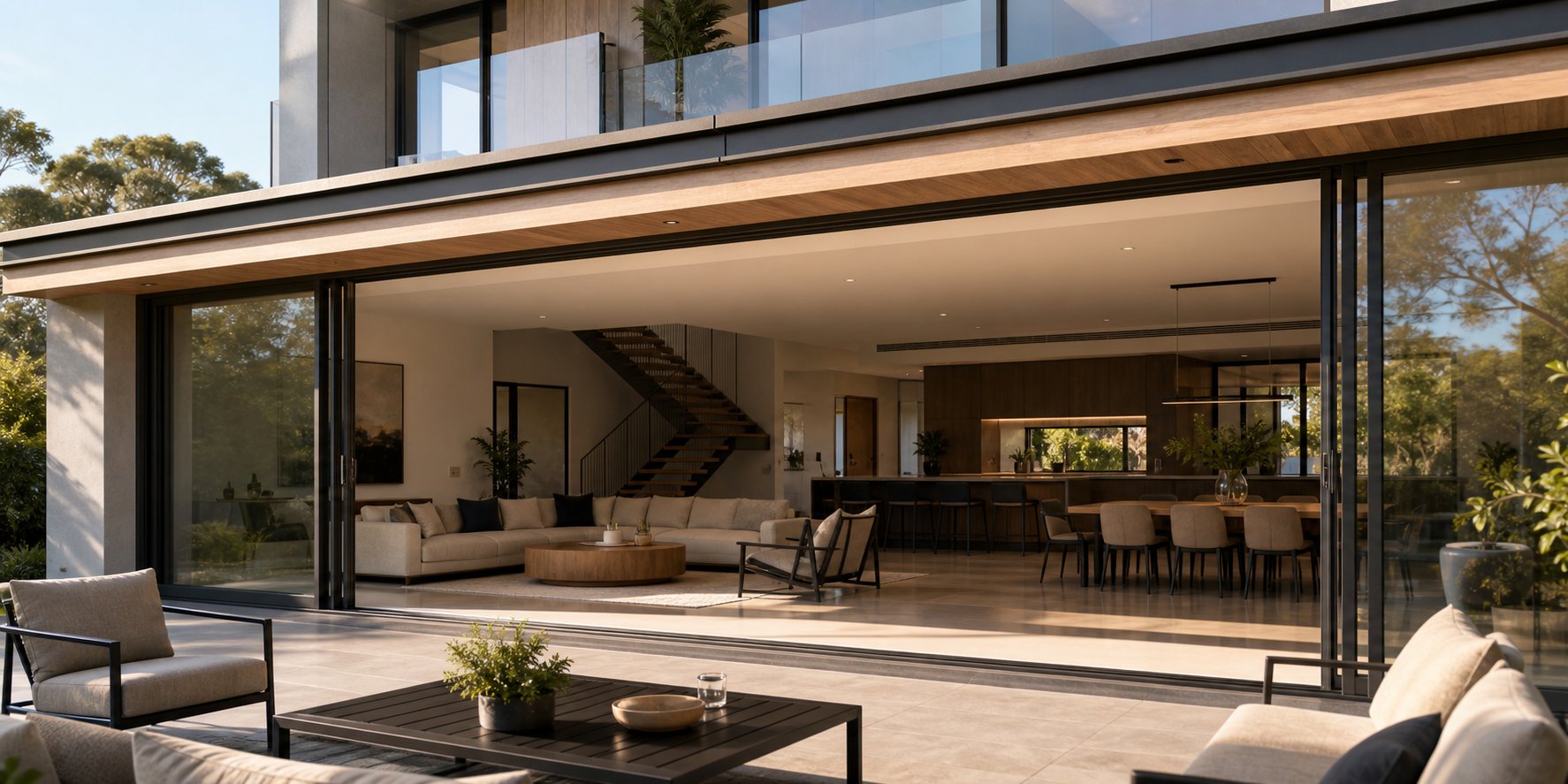
A fixed panel and a heavy sliding door might sit in identical openings, yet the forces acting on their fixings have almost nothing in common. Wind loads apply universally, but each window type adds its own operational forces — forces generated every time someone opens, closes, or locks a sash. These operational loads concentrate at specific points around the frame perimeter, and the fixing detail must reinforce those points accordingly. Treating every window type with the same generic fixing schedule ignores the mechanical reality of how each one actually works.
Sliding Window Fixing for Track Load Support
Sliding window installation introduces lateral and vertical forces that other window types do not generate. When a sash slides along its track, the weight of the glazed panel bears down on the sill track rollers while lateral force pushes against the head guide channel. Over thousands of open-close cycles, these concentrated loads can loosen head and sill fixings if the anchoring at track support points is inadequate.
Understanding how to install a sliding window properly means recognising that the sill track is a structural element, not just a guide. The full dead load of the operable panel — often 30 kg to 60 kg for a double-glazed residential sash — rides along this track. Fixings at the sill must anchor the track firmly enough to resist deflection under that rolling weight without pulling away from the substrate. Additional fixings are required at track junction points where the sill rail meets the jamb members, since these corners experience the highest stress concentration during operation.
At the head, the guide channel keeps the sash from swinging inward under wind suction. Fixings here must resist intermittent outward pull forces as wind loads cycle. For wide openings common in Australian living areas — three-panel or four-panel sliders spanning 3000 mm or more — head track deflection becomes a design consideration. The deflection limit for members supporting glass is typically no less than span/175 to span/180, meaning fixings must be close enough to keep the head rail within that tolerance under full wind load.
If you ever need to know how to put a sliding window back in frame after removing a sash for cleaning or maintenance, the same track integrity matters. A sash that lifted out easily at installation but now resists re-engagement often indicates head track deflection or sill track shift caused by inadequate fixing at support points.
Casement and Awning Hinge Zone Reinforcement
Casement and awning windows generate lever-arm forces that concentrate almost entirely on the hinge side of the frame. When a sash swings open, its weight acts through the hinge pivot and pulls the jamb member outward at the top hinge while pushing inward at the bottom. This rotational force pattern demands reinforced fixing at and immediately adjacent to every hinge position.
The lever arm increases with sash size. A large casement sash — say 600 mm wide and 1500 mm tall with double glazing — can generate significant rotational pull at the top hinge, especially when held open in wind. Jamb fixings closest to the hinge positions carry this load directly into the wall substrate. If these fixings are spaced at standard 600 mm centres and happen to fall midway between hinges rather than aligning with them, the frame flexes at precisely the point where it should be most rigid.
Best practice places dedicated fixings within 100 mm above and below each hinge location on the jamb, in addition to the standard fixing schedule. For awning windows, the same principle applies but rotated: hinges sit at the head, so the head fixings bear the operational lever-arm forces while the sill fixings handle the lock-side pull. This is one reason awning windows in high-wind coastal zones require closer head fixing centres than a standard fixed panel in the same position.
Mullion and Transom Connections in Multi-Panel Assemblies
Large glazed openings rarely consist of a single frame. Multi-panel assemblies combine fixed lights, operable sashes, and sometimes different window types within a single structural opening, connected by vertical mullions and horizontal transoms. These intermediate members carry loads from every panel they adjoin and transfer those loads down to the sill or across to the jamb fixings at the perimeter.
A supporting mullion must resist the highest design lateral forces (usually wind) acting on its tributary area — the half-width of glass on each side. Deflection control is critical: mullions holding glass must stay within span/175 to span/180 to prevent seal failure at the glazing rebate. For larger or more complex openings that exceed what an aluminium mullion alone can handle, a structural steel or timber frame behind the visible aluminium provides the primary support, with the aluminium profiles clipped or mechanically fastened to the structural backing.
Connections between mullions, transoms, and the perimeter frame introduce concentrated point loads at each intersection. These are typically mechanical connections — screw-fixed cleats, crimped spigot joints, or bolted angle brackets depending on the system. Each connection point must transfer wind load, dead load (the weight of glass above), and any operational forces from adjacent operable panels without introducing flex or play.
Transom connections are particularly demanding in stacked configurations where an operable sash sits above a fixed panel. The transom carries the dead weight of the upper panel while simultaneously resisting wind load as a spanning member. Fixing the transom back to the structure — either directly into a masonry reveal or via a bracket to a structural mullion — prevents the member from deflecting beyond acceptable limits under combined loading. Reactions at the ends of these structural supports can be substantial, requiring larger anchor plates or multiple fasteners to distribute the concentrated force into the host structure.
The key takeaway for multi-panel assemblies is that perimeter fixings alone are not sufficient. Every intermediate mullion and transom either needs its own anchor back to the building structure or must be engineered as part of a self-supporting frame system where internal connections carry loads to the anchored perimeter. The choice depends on opening size, wind classification, and the structural capacity of the surrounding wall — factors that shift significantly based on the climate and exposure conditions specific to each project site.
Climate Exposure and Thermal Performance at Fixing Points
Site-specific climate conditions do not just influence which window product you select — they directly alter how that product must be anchored to the building. A nail fin window detail suitable for a sheltered suburban block in Adelaide would be dangerously under-specified on an exposed headland in Wollongong. Wind classification, coastal proximity, rainfall intensity, and temperature range each feed into the fixing schedule, determining how close together anchors must sit, what pull-out strength they need, and which materials will survive the environment long-term.
Wind Zone Classification and Fixing Centre Adjustments
In Australia, wind classification for windows follows AS 2047, which references AS/NZS 1170.2 for site-specific wind pressure calculations. The system assigns classifications from N1 (lowest residential) through N6 and C1 through C4 (cyclonic regions in northern Queensland, the Northern Territory, and parts of Western Australia). Each step up the classification scale translates to higher design pressures acting on the glazed panel, which means greater pull-out and shear forces at every fixing point around the frame perimeter.
The relationship is direct: higher wind pressure requires either stronger anchors, closer fixing centres, or both. A window rated for N3 conditions might perform adequately with fixings at 600 mm centres in solid masonry. The same frame in an N5 or C2 zone could need centres reduced to 300 mm with upgraded anchors providing substantially higher pull-out resistance. Corner zones of a building, where wind pressures intensify due to aerodynamic effects, often require even tighter spacing regardless of the overall site classification.
Reading a wind load table and translating it into a fixing schedule involves three steps. First, determine the design wind pressure acting on the window (in kilopascals) based on the site’s wind region, terrain category, shielding, and building height — all derived from AS/NZS 1170.2. Second, calculate the tributary area each fixing must support: the width of frame between adjacent fixings multiplied by the depth of glass that loads onto that frame member. Third, confirm that the selected anchor’s pull-out capacity in the specific substrate exceeds the force generated by that design pressure acting over the tributary area, with an appropriate safety factor applied.
Exposure category concepts parallel those found in international wind codes. Terrain roughness classifications range from built-up suburban areas (which slow wind through friction and turbulence) to open coastal terrain where wind accelerates unimpeded across water. In Australian terms, terrain category 3 (suburban, with surrounding buildings and trees) produces significantly lower design pressures than terrain category 1 (exposed coastline with no upwind obstructions). Aluminium sliding windows in Sydney’s eastern suburbs facing the ocean, for instance, sit in a far more aggressive exposure category than an identical unit installed in a western suburb shielded by kilometres of built-up residential fabric.
The practical consequence for fixing schedules is significant. A project in terrain category 1 with cyclonic wind loading may demand fixing centres as tight as 200 mm to 300 mm with chemical anchors rated above 10 kN pull-out. A sheltered inland project in terrain category 3 might safely use standard mechanical anchors at 600 mm centres. The table below provides a simplified framework mapping exposure severity to recommended fixing parameters.
| Exposure Category | Typical Australian Context | Max Fixing Centres | Min Anchor Pull-Out Strength |
|---|---|---|---|
| Low (N1–N2, TC3) | Sheltered suburban, inland, surrounded by buildings | 600 mm | 3.0 kN per fixing |
| Moderate (N3–N4, TC2–TC3) | Semi-exposed suburban, elevated sites, moderate coastal setback | 450 mm | 5.0 kN per fixing |
| High (N5–N6, TC1–TC2) | Exposed coastal, high-rise upper levels, open rural | 300 mm | 8.0 kN per fixing |
| Cyclonic (C1–C4, TC1) | Tropical coastal QLD, NT, northern WA | 200–300 mm | 10.0+ kN per fixing |
These figures serve as a starting framework. Actual fixing schedules must be engineered for each project based on the specific window size, aspect ratio, and substrate type. Larger panels with greater tributary areas per fixing demand higher-capacity anchors even in moderate zones. How to replace a sliding window on an exposed facade, for example, requires reassessing the existing fixing schedule against current wind code requirements — older installations may not meet the updated AS 2047 classifications introduced in recent NCC revisions.
Thermal Bridging at Fixing Points and Mitigation Strategies
Every metal bracket or screw that passes through the insulation zone at the frame-to-wall junction creates a localised thermal bridge. Heat (or cold) conducts along the fastener, bypassing the insulation and thermal break built into the aluminium profile. Research into thermal bridging around windows confirms that even with high-performance thermally broken frames, incorrectly detailed fixing connections can maintain high linear thermal losses and create condensation risk at the internal reveal.
The impact scales with the number and conductivity of fixings. A direct-fix screw driven through the frame and into a masonry reveal bridges the full insulation depth. A lug bracket mounted behind the insulation line and anchored into the structure can keep the conductive path shorter or offset it entirely from the thermal envelope. Steel brackets conduct roughly 50 times more heat than the surrounding insulation, so even a few poorly positioned fixings create measurable cold spots visible on thermal imaging surveys.
Mitigation strategies for thermal bridging at fixing points include:
- Thermally isolating brackets — Using nylon or composite packer pads between the metal bracket and the aluminium frame, breaking the conductive bridge at the most critical interface.
- Positioning fixings behind the insulation line — Lug and cleat systems allow the anchor point to sit on the structural side of the insulation layer, so the bracket does not penetrate the thermal envelope at all.
- Reducing fastener count where structurally acceptable — Fewer fixings mean fewer thermal bridges, provided the remaining fixings have adequate capacity for the design loads. This is a direct trade-off between thermal performance and structural anchoring that must be resolved through engineering rather than guesswork.
- Using lower-conductivity fastener materials — Stainless steel conducts less heat than mild steel, though neither approaches true insulation. In passive house or high-performance builds, fibreglass or composite fixing brackets are emerging as solutions, though their load ratings remain lower than metal equivalents.
- Wrapping insulation over bracket faces — Where brackets must sit within the insulation zone, adding a thermal insulation cover over the exposed metal surface reduces the radiation and convection component of heat loss at that point.
For Australian projects targeting NatHERS ratings above 7 stars or compliance with the NCC Section J energy provisions, thermal bridging at fixing points can meaningfully affect the modelled U-value of the window-to-wall junction. A poorly detailed nail fin window detail with uninsulated steel clips at 450 mm centres may degrade the effective thermal performance of a thermally broken frame by 10 to 15 percent — enough to push a marginal energy assessment below compliance thresholds.
Climate and exposure do not just dictate structural anchoring requirements. They also determine how much thermal performance you can afford to lose at fixing points, which materials will survive in the local environment without degrading, and how aggressively moisture will attack any weakness in the weather seal. These environmental factors shape the fixing detail from the outside in, while the project’s design intent, coordination between trades, and supplier capability shape it from the inside out — and that convergence is where successful installation planning begins.
Planning Your Installation and Getting Fixing Details Right
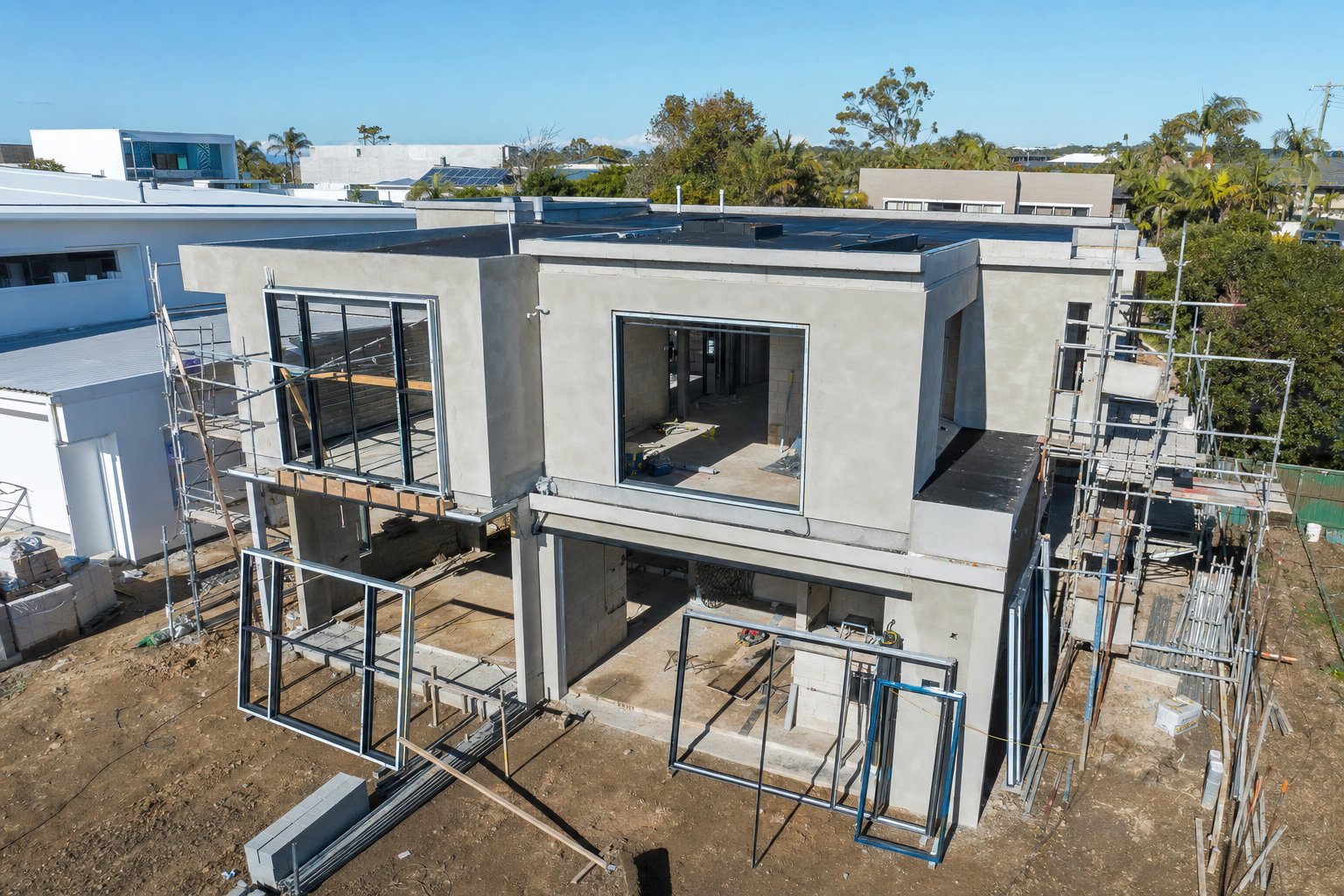
Substrate, exposure, window type, sealant sequencing, material compatibility — every layer of complexity explored in this guide converges on a single practical reality: aluminium window fixing details must be resolved before fabrication begins, not improvised on site. The window that arrives at your project has already been manufactured to specific dimensions, with specific fixing hole locations, specific bracket provisions, and specific clearance assumptions baked into the profile design. If the fixing detail was never coordinated with the actual wall conditions, no amount of site adjustment will recover what should have been decided at the planning stage.
Why Fixing Details Must Be Resolved Before Fabrication
Fabrication locks in geometry. Once an aluminium frame is welded, crimped, or mechanically joined, its fixing hole positions, mullion connection points, and sub-sill drainage provisions are fixed. A frame fabricated for direct-fix installation cannot easily be retrofitted with lug brackets on site. A sliding window manufactured without adequate head clearance for lintel deflection will bind after the first summer. Replacing sliding windows that were incorrectly specified from the start often costs more than getting the detail right upfront, because the replacement involves stripping finishes, modifying the structural opening, and resequencing the weatherproofing layers from scratch.
The window schedule — that itemised document listing every opening’s dimensions, type, glazing, and hardware — should also carry fixing method information for each location. As project documentation best practice confirms, jamb, head, and sill details are integral schedule components that need to be locked in during the construction documentation phase, not left as assumptions for the installer to resolve. When schedules omit fixing details, the information gap cascades into procurement delays, site rework, and weatherproofing failures that only reveal themselves months after handover.
For anyone figuring out how to replace sliding windows in an existing opening, the same principle applies in reverse. The existing substrate condition, fixing centres of the original installation, and any degradation at anchor points must be surveyed and documented before ordering replacement units. A new frame sized to the old rough opening but specified for a different fixing method may not align with the available substrate or the existing weatherproofing membrane positions.
Coordinating Between Supplier, Builder, and Designer
Fixing details sit at the intersection of three disciplines. The designer specifies the opening sizes, wind classification, and thermal performance targets. The builder knows the actual wall substrate, site tolerances, and construction sequence. The window supplier understands the aluminium system’s fixing provisions, bracket options, and clearance requirements. No single party holds all the information needed to produce a complete fixing detail — it requires active coordination between all three.
That coordination works best when the supplier is engaged early enough to review structural drawings, confirm substrate types, and recommend fixing methods before the window schedule is finalised. A project-capable aluminium window partner brings more than just product — they contribute system knowledge that bridges the gap between what the architect has drawn and what the builder can practically install. From reviewing window schedules and recommending profile systems through to material calculations, manufacturing coordination, quality control, and delivery planning, the right supplier streamlines a process that otherwise fragments across multiple trades and timelines.
For builders, developers, architects, and contractors working across Australian residential and commercial projects, the practical takeaway is this: how to replace a sliding window correctly, or how to install one for the first time, depends entirely on decisions made well before anyone picks up a drill. Engage your supplier with drawings, not just measurements. Provide substrate information, not just opening sizes. And confirm fixing details in writing as part of the procurement process — because once fabrication begins, the fixing strategy is committed whether anyone planned it or not.
Frequently Asked Questions About Aluminium Window Fixing Details
1. What are aluminium window fixing details and why are they important?
Aluminium window fixing details are technical specifications that define how a window frame anchors into a structural opening. They cover bracket types, fastener positions, embedment depths, sealant sequencing, and load paths from frame to substrate. These details matter because they govern structural integrity under wind and operational loads, maintain weatherproofing continuity at every penetration point, prevent thermal bridging at the frame-to-wall junction, and ensure the installation performs reliably over decades. Without substrate-specific fixing information, installers risk using incorrect anchors, inadequate spacing, or incompatible materials that lead to water ingress, frame distortion, or anchor pull-out.
2. What fixing method is best for aluminium windows in AAC or lightweight block walls?
AAC blocks have roughly one-quarter the compressive strength of standard concrete, so standard expansion anchors can pull through under load. Specialist AAC nylon frame plugs or chemical resin anchors with perforated sleeves are recommended. Chemical anchors bond with the porous AAC structure to create a mass around the threaded rod that resists pull-out far better than friction-based mechanical fasteners. Minimum embedment depth should be 75 mm to 80 mm, substantially deeper than the 50 mm typical for solid concrete. Maximum fixing centres should tighten to 400 mm, with closer spacing in high-wind or exposed locations. Every fixing point also needs a packer behind the frame to spread bearing load and prevent the aluminium from crushing into the soft block face.
3. How do you prevent galvanic corrosion when fixing aluminium window frames?
Galvanic corrosion occurs when aluminium contacts a more noble metal in the presence of moisture. Prevention centres on material selection and isolation. Zinc-plated or hot-dip galvanised steel fasteners are generally compatible because zinc sits close to aluminium on the galvanic series. Stainless steel screws are acceptable in most environments provided the stainless component is small relative to the aluminium surface area, though nylon washers or EPDM gaskets should isolate the contact in severe marine zones. Bare mild steel, brass, bronze, and copper must never contact aluminium directly. Non-conductive spacers or polymeric coatings between the fixing and the aluminium profile break the electrical circuit entirely, eliminating the galvanic cell regardless of environmental severity.
4. Why must aluminium window fixing details be resolved before fabrication?
Fabrication locks in the frame geometry permanently. Fixing hole positions, mullion connection points, bracket provisions, and sub-sill drainage configurations are all committed once the aluminium is welded or crimped. A frame fabricated for direct-fix installation cannot easily accommodate lug brackets on site. A sliding window manufactured without adequate head clearance for lintel deflection will bind after thermal cycling. Resolving fixing details before fabrication ensures the window arrives with correct provisions for the actual wall substrate, exposure conditions, and construction sequence. This coordination between designer, builder, and supplier prevents costly rework, procurement delays, and weatherproofing failures that only surface months after handover.
5. How does wind zone classification affect aluminium window fixing centres in Australia?
Australian wind classifications under AS 2047 range from N1 (lowest residential) through to C4 (cyclonic regions). Each step up the scale increases the design wind pressure acting on the glazed panel, which directly increases pull-out and shear forces at every fixing point. In sheltered suburban locations rated N1 to N2, fixing centres of 600 mm with anchors providing around 3.0 kN pull-out are typically adequate. Moderate exposure at N3 to N4 tightens centres to 450 mm with 5.0 kN anchor capacity. High-exposure coastal or elevated sites at N5 to N6 may require 300 mm centres with 8.0 kN anchors, while cyclonic regions can demand centres as tight as 200 mm with chemical anchors rated above 10 kN. Building corner zones often require even closer spacing due to aerodynamic pressure intensification.
More Window & Door Guides