
What Is Aluminium Window Head Flashing
Window flashing is the system of waterproofing materials installed around a window opening to prevent water from penetrating the wall assembly. Within that system, aluminium window head flashing is a formed metal component fixed above the window frame — specifically at the window head, which is the top horizontal member of the opening. Its job is simple but critical: intercept water running down the wall face and redirect it outward, away from the rough opening and onto the exterior cladding below.
Head flashing is a rigid metal drip edge installed directly above the window frame that diverts water away from the rough opening to prevent moisture intrusion behind the cladding.
Without this component, water that travels down an exterior wall has a direct path into the gap between the window frame and the surrounding framing. That gap — even when sealed with tape or sealant — becomes a vulnerability over time, particularly in Australian climates with heavy coastal rainfall or wind-driven rain exposure.
What Head Flashing Does at the Top of Your Window
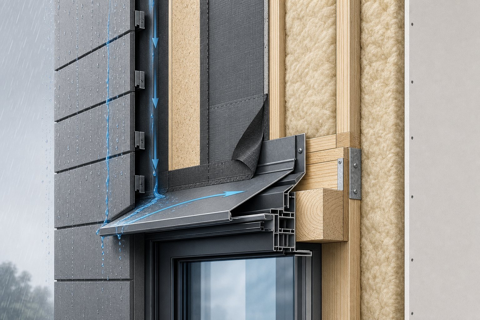
Think of window head flashing as a small awning built into the wall assembly. It sits above the window frame, tucked behind the cladding, with a projecting drip edge that kicks water outward. Any moisture running down the wall surface or behind the cladding hits the flashing and gets directed away from the window heads before it can pool at the top of the frame. It works passively — no moving parts, no maintenance — but only if it is correctly sized, correctly positioned, and properly integrated with the water-resistive barrier behind.
Head Flashing vs Sill Flashing vs Jamb Flashing
A complete window flashing system covers all four perimeter edges of the rough opening. Each component handles a different position and a different water management challenge:
- Head flashing (top): A rigid metal drip cap that diverts water flowing down the wall away from the top of the window frame. Typically aluminium, installed behind the cladding with the drip edge projecting outward.
- Sill flashing (bottom): A sloped pan or membrane at the base of the rough opening that collects any water reaching the bottom of the frame and drains it to the exterior. Must slope outward to function.
- Jamb flashing (sides): Flexible membrane tape applied to the vertical edges of the opening, overlapping the sill below and tucking under the head flashing above. Follows the shingle-lap principle — each layer overlaps the one beneath it.
Every layer depends on the one below it. The sill goes in first, then the jambs, then the head flashing last. This sequencing ensures water always drains downward and outward rather than pooling behind any component. Getting the order wrong — even at one corner — creates a pocket that traps moisture against the framing, and damage can progress silently for years before any visible signs appear inside.
The window head is the most leak-prone location in the entire assembly because it faces the full volume of water running down the wall above. That makes understanding the building science behind water movement essential to getting the installation right.
Building Science Behind Window Head Flashing
Water has two reliable allies when attacking a building envelope: gravity and wind. In calm conditions, rain falls vertically and runs straight down exterior wall surfaces. During storms — particularly the wind-driven events common across coastal and exposed regions of Australia — rain travels at steep angles, hitting walls with horizontal force that pushes moisture into joints, gaps, and transitions. Either way, the water ends up moving downward across the cladding until it meets an obstruction. The horizontal junction above a window frame is one of the most significant obstructions on any wall face, and it creates a natural pooling point where water concentrates before finding a way in.
How Water Moves Above Your Windows
Picture a wall during a heavy downpour. Water sheets down the cladding surface in a thin film, driven by gravity alone on a still day or forced sideways by gusts during a storm. When that flowing water reaches the top of a window opening, it encounters a horizontal break in the wall plane — a gap between the cladding edge and the window frame below. Some water will drip off the cladding edge and fall harmlessly past the window. But a portion follows surface tension along the underside of the cladding, creeps inward toward the rough opening, and enters the cavity behind the wall face.
This is where flashing for windows becomes essential. A properly formed head flashing intercepts that downward water flow before it reaches the vulnerable gap. The drip edge projects outward from the wall face, breaking surface tension so water falls free of the building rather than tracking inward. Any moisture that has already penetrated behind the cladding — through joints, cracks, or fastener holes higher up the wall — hits the back leg of the flashing and gets redirected outward in the same way.
The window head is the most leak-prone area of any window installation for a straightforward reason: it collects the cumulative water volume from the entire wall area above it. A window on the ground floor of a two-storey home receives runoff from metres of wall surface. Add wind pressure, and you have a high volume of water arriving at speed at the single most vulnerable transition point in the assembly.
The Role of the Water-Resistive Barrier
Flashing on windows does not work in isolation. It functions as one component within a layered drainage system, and its performance depends entirely on correct integration with the water-resistive barrier (WRB) — the sheet membrane or building wrap installed over the structural sheathing behind the cladding.
The fundamental principle is gravity-driven drainage. Every layer in the wall assembly must lap over the layer below it, just like roof tiles or weatherboards, so water always flows outward and downward without finding a path behind any component. The WRB must lap over the top leg of the head flashing — never tuck behind it. This single window flashing detail is responsible for more installation failures than any other error. When reversed, water running down the face of the WRB drains directly behind the flashing and into the rough opening, bypassing the very component installed to prevent that outcome.
The correct water management sequence follows a logical chain from exterior to interior:
- Rain hits the exterior cladding surface and runs downward via gravity.
- Water that penetrates behind the cladding meets the WRB and continues draining downward along its face.
- The WRB, lapped over the top leg of the head flashing, delivers water onto the flashing surface.
- The head flashing redirects that water outward, past its drip edge, and onto the face of the cladding below the window.
- Water continues draining down the cladding face below, eventually reaching the base of the wall and exiting through weep holes or a bottom termination detail.
Every step in this sequence relies on the one above it performing correctly. A break at any point — a reverse lap, a missing end dam, a flashing that terminates short of the opening width — sends water into the wall cavity where it can saturate timber framing, corrode steel components, and promote mould growth long before any stain appears on interior plaster. Understanding these window flashing details at a physics level is what separates a weathertight installation from one that fails silently over years.
The building science is clear: gravity is reliable, and drainage systems that work with gravity succeed. The question that follows is which materials best serve this function over the long term — and why aluminium has become the default choice for residential head flashing across Australia.
Material Options for Head Flashing Compared
Five materials realistically compete for use as window head flashing in Australian residential construction: aluminium, galvanized steel, copper, PVC drip caps, and self-adhesive membrane flashing tape. Each handles water the same way in principle — intercept and redirect — but they differ sharply in longevity, cost, and how well they tolerate Australian conditions over decades of service.
Aluminium vs Galvanized Steel vs Copper
Aluminium window flashing dominates the residential market for good reason. It is lightweight, naturally corrosion-resistant, easy to bend and custom-form on site, and costs a fraction of what copper demands. The metal develops a self-healing oxide layer that protects the surface without any applied coating, which makes it particularly well suited to coastal and high-humidity environments where salt spray accelerates the failure of other metals. Aluminium flashings hold up for 50 years or more in typical Australian conditions, and pre-finished options with Kynar coatings extend that further while matching cladding colours.
Galvanized steel is the budget option. It is stiffer than aluminium at the same gauge, holds bends cleanly, and costs roughly 20 to 30 percent less. The trade-off is vulnerability to salt. The zinc coating that protects the underlying steel gets consumed over time, and in coastal zones — anywhere within about 10 kilometres of saltwater — galvanized metal window flashing can show rust-through within 8 to 12 years. Cut edges where the zinc is removed fail first. For inland sites with dry, clean air, galvanized steel delivers solid performance at the lowest upfront cost and can last 20 to 30 years without issue.
Copper sits at the premium end. It is effectively permanent — measured in centuries, not decades — and develops a patina that many architects consider a design feature. However, copper costs three to five times more than galvanized for the same project, and it introduces a serious compatibility problem. Copper runoff stains lighter cladding materials, and its position on the galvanic series means it aggressively corrodes aluminium or steel components it contacts. For most residential projects, copper is architectural rather than practical — specified for heritage restoration or premium custom builds where budget is secondary to appearance and longevity.
PVC drip caps offer a non-metallic alternative at low cost. They resist corrosion entirely and install quickly over vinyl window frames. The downside is rigidity under UV exposure — Australian sun degrades PVC over time, causing brittleness and cracking, particularly on north- and west-facing elevations. PVC suits short-term or budget-constrained applications but lacks the decades-long durability of metal flashing for windows.
When Membrane Tape Complements Rigid Flashing
Self-adhesive membrane flashing tape is not a replacement for rigid head flashing — it is a complement. Membrane tape excels at sealing the rough opening, wrapping corners, and creating a secondary drainage layer beneath the rigid metal component. Where rigid aluminium provides the structural drip edge that kicks water outward, membrane tape handles the transitions and joints where rigid material cannot conform tightly enough to irregular surfaces.
The strongest installations use both: membrane tape integrated with the WRB at the rough opening, then rigid aluminium over the top to provide the projecting drip edge and long-term structural integrity. Using membrane tape alone leaves no positive drip — water tracks along the underside via surface tension rather than being thrown clear of the wall.
One critical consideration across all window flashing metal options is galvanic corrosion. Aluminium sits relatively low on the galvanic series, meaning it corrodes preferentially when in direct contact with more noble metals like copper or mild steel in the presence of moisture. The practical rule: always use stainless steel or aluminium fasteners with aluminium flashings, never plain steel. Isolate aluminium from copper with EPDM washers or neoprene separators. And avoid running copper drainage onto aluminium surfaces below — the dissolved copper ions attack the aluminium even without direct contact.
| Material | Durability | Cost (Relative) | Ease of Installation | Corrosion Resistance | Best Use Case |
|---|---|---|---|---|---|
| Aluminium | 50+ years | Moderate | High — bends easily on site, lightweight | Excellent — self-healing oxide layer, salt tolerant | General residential, coastal and exposed sites |
| Galvanized Steel | 20–30 years (inland); 8–12 years (coastal) | Low | High — stiff, holds bends well | Moderate — zinc sacrificial layer fails faster in salt air | Inland residential, sheltered urban sites |
| Copper | 100+ years | Very High (3–5x galvanized) | Moderate — soft, forms well but requires special fasteners | Excellent — permanent patina protection | Heritage restoration, premium architectural projects |
| PVC Drip Cap | 15–25 years | Low | Very High — snaps or slides into place | Complete (non-metallic) but UV-degradable | Budget applications, vinyl window systems |
| Self-Adhesive Membrane Tape | 20–30 years (concealed) | Low–Moderate | High — peel and stick, conforms to irregular shapes | Excellent when concealed from UV | Secondary layer beneath rigid flashing, rough opening sealing |
For most Australian homes — whether coastal brick veneer in Sydney, weatherboard in Melbourne, or rendered construction in Brisbane — aluminium delivers the best balance of cost, longevity, and performance. It handles the country’s salt-laden coastal air without the premature failure of galvanized steel, costs a fraction of copper, and forms easily to suit any window metal flashing profile a builder needs on site. The material choice is settled for the majority of projects. What varies more significantly is the gauge thickness and sizing — decisions that directly affect whether that aluminium performs as intended over its full lifespan.
Gauge Thickness and Sizing for Window Head Flashing
Aluminium is the right material for most projects, but selecting the wrong thickness turns a good material into a poor-performing component. The gauge you choose affects rigidity, formability, resistance to thermal buckling, and how well the flashing holds its profile over years of weather exposure. Getting this window head flashing detail right means matching the gauge to the span and the sizing to the wall assembly.
Choosing the Right Gauge for Your Application
Aluminium coil stock for residential metal head flashing is sold in several standard thicknesses. Thinner material bends more easily and costs less, but it flexes under wind load and can develop oil-canning — that rippled, wavy distortion across the face — on wider spans. Thicker aluminium resists buckling from thermal expansion and holds its formed shape more reliably, though it demands more force to bend and carries a higher price per metre.
For standard window openings up to around 900 mm wide, 0.5 mm stock handles the job well. Windows between 900 mm and 1500 mm benefit from stepping up to 0.6 mm or 0.7 mm to maintain a flat, rigid profile across the span. Anything wider — large picture windows, stacking sliders, or multi-panel configurations — calls for 0.7 mm or 0.8 mm material. At those widths, lighter gauges sag visibly between fastening points and lose the positive slope that keeps water draining outward at the top of window flashing.
| Gauge (Thickness) | Millimetres | Typical Application | Recommended Max Span |
|---|---|---|---|
| Light | 0.5 mm | Standard single windows, narrow openings | Up to 900 mm |
| Medium | 0.6 mm | Mid-size windows, paired units | 900–1500 mm |
| Heavy | 0.7 mm | Wide openings, exposed elevations | 1500–2400 mm |
| Extra Heavy | 0.8 mm | Large picture windows, commercial-grade window cap flashing | 2400 mm+ |
Siding brakes commonly used on residential sites can bend aluminium up to about 0.7 mm without difficulty. The 0.8 mm range sits at the upper limit for most portable brakes and may require shop fabrication or a heavier-duty machine.
Sizing the Back Leg and Drip Edge
Gauge is only half the equation. The overall width of the flashing blank — before bending — determines how far up the wall the back leg extends and how far the drip edge projects outward. Both dimensions respond directly to climate exposure and the depth of the window recess within the wall assembly.
The back leg is the vertical portion that runs up the wall sheathing behind the WRB. In sheltered inland locations with moderate rainfall, 50 mm of back leg height meets code requirements comfortably. In rain-heavy coastal zones or on upper storeys where water volume concentrates, increasing the back leg to 75 mm or even 100 mm adds insurance against water bypassing the flashing during extreme weather. The window header flashing detail that works in a protected single-storey home in Adelaide may underperform on an exposed upper-floor elevation facing prevailing weather in coastal Queensland.
The drip edge projection — the portion that extends outward over the face of the cladding or window trim below — needs enough throw to break surface tension. A minimum of 10 mm projection clears water from the wall face; 15 to 20 mm is better for window top flashing on exposed facades where wind can push water back against the building. A hemmed drip edge, where the metal folds back on itself at the bottom, creates a cleaner break point and prevents the cut edge from wicking water via capillary action.
- Back leg height: Minimum 50 mm for sheltered sites; 75–100 mm for exposed, multi-storey, or high-rainfall locations.
- Drip edge projection: Minimum 10 mm; 15–20 mm recommended for exposed elevations. Hem the edge for a clean water break.
- End dams: Required at both ends of the flashing. Height should match or exceed the back leg to contain water running laterally along the flashing face.
- Overall blank width: Add back leg + face (depth of window recess from sheathing to cladding face) + drip projection + hem allowance. Measure the actual assembly — do not assume standard dimensions.
- Length: Extend the flashing at least 25 mm past the window opening on each side, plus additional material for forming end dams.
Climate zone directly shapes these decisions. A window flashing diagram drawn for a temperate, inland build looks different from one designed for a cyclone-prone northern site or a salt-exposed coastal elevation. The sizing is not decorative — every millimetre of back leg and drip projection earns its place by managing real water volume under real weather loads.
With the correct gauge and dimensions established, the next consideration is how that flashing physically integrates with the cladding system — because the profile, termination, and positioning change depending on whether the wall is clad in weatherboard, fibre cement, brick veneer, or render.

How Head Flashing Integrates with Different Cladding
A perfectly sized piece of aluminium means nothing if it does not fit the wall assembly it is installed in. The cladding system dictates where the flashing sits, how the drip edge terminates, and whether the profile needs to be custom-bent with additional legs or returns. Australian homes use a range of exterior wall coverings — weatherboard, fibre cement, brick veneer, and rendered systems are the most common — and each one demands a different approach to exterior window flashing integration.
Regardless of cladding type, the head flashing must always direct water outboard of the cladding plane. If the drip edge terminates behind or flush with the cladding face, water re-enters the wall cavity and the flashing serves no purpose.
Head Flashing with Lap Siding and Fibre Cement
Weatherboard and fibre cement lap siding share a similar integration principle. The flashing tucks behind the course of cladding directly above the window, with the drip edge projecting outward over the window trim flashing zone — that junction where the top of the frame or head trim meets the cladding below. This creates a shingle-lap arrangement: cladding overlaps flashing, flashing overlaps window frame, and water cascades outward at every layer.
- Weatherboard (timber or composite lap siding):
- Back leg sits flat against sheathing, under the WRB lap
- Drip edge projects 15–20 mm beyond the cladding face
- The weatherboard course above overlaps the back leg by a minimum of 25 mm
- End dams required at both ends to prevent lateral water runoff into the wall cavity
- Aluminium flashing for siding applications works well here because the light material tucks easily behind flexible cladding courses
- Fibre cement panels:
- Integration mirrors weatherboard in horizontal lap configurations
- Sheet panel systems (vertical or large-format) require the flashing to sit behind the sheet joint or behind a horizontal cover strip above the window
- Panel rigidity means the flashing profile must match the cladding depth precisely — any gap between the back of the panel and the flashing face allows wind-driven rain to bypass the drip edge
- End dams are essential, particularly on wide windows where water volume concentrates
In both cases, the aluminium profile is relatively simple: a back leg, a flat face that bridges the cavity or furring depth, and a projecting drip edge. Portable sheet metal brakes handle this easily on site, and the lightweight material makes flashing around window openings in lap-clad walls a straightforward task for any competent builder.
Head Flashing in Brick Veneer and Stucco Systems
Brick veneer and rendered walls introduce more complexity. The cladding is thicker, the cavity is deeper, and in the case of masonry, additional structural elements are already present above the opening.
- Brick veneer:
- A steel lintel (angle iron) carries the brickwork above the window — the head flashing does not replace this structural element
- The flashing sits on top of the lintel, with its back leg running up the inner wall behind the WRB
- The drip edge projects outward beyond the face of the brick, kicking water clear of the masonry below
- End dams must be tall enough to contain any water pooling on the lintel surface
- A weep system — open perpend joints or weep vents — at the lintel level works in conjunction with the flashing to drain the cavity behind the brick leaf
- The flashing profile is custom-bent to span the full cavity depth (typically 40–50 mm) plus the brick face, requiring a wider blank than lap siding applications
- Stucco and render systems:
- Rendered walls apply a continuous coat over mesh or directly over substrate, leaving no natural overlap point for the flashing to tuck behind
- The back leg extends up behind the render system and WRB; the drip edge must project proud of the finished render face
- A control joint or render stop bead above the drip edge conceals the transition and prevents render from bridging over the flashing
- Metal flashing around windows in rendered systems requires careful attention to sealant compatibility — some render products react with bare aluminium, so powder-coated or pre-finished flashing prevents staining
- End dams are critical because rendered walls offer no visible drainage path for water that runs off the ends of the flashing
For metal building window flashing applications — steel-clad sheds, industrial builds, or homes with metal sheet cladding — the same principles apply but the profile adjusts again. The flashing typically hooks behind the sheet rib above the window and projects over the face below, with purpose-made foam closure strips sealing the corrugated profile against wind-driven rain entry.
Every cladding type demands a different profile, but the logic never changes. Water must always reach the drip edge and fall clear of the building. Custom-bending the flashing to match the exact depth of each wall assembly is what makes flashing exterior windows effective across every construction method common in Australian residential and commercial builds. When the profile fits the assembly, the physics works. When it does not — when the drip edge sits too close to the wall or ends short of the cladding face — water finds the path of least resistance back into the cavity.
The cladding dictates the shape of the flashing. The next question is whether one layer of that shaped aluminium is enough, or whether certain conditions call for a second line of defence beneath it.
One Layer or Two Layers of Head Flashing
Browse any building science forum long enough and you will find this argument in full swing: should head flashing for windows be a single rigid component, a rigid layer plus a membrane underneath, or — in some cases — nothing separate at all? The debate generates strong opinions but rarely a clear framework. Here is one.
The One-Layer Baseline Approach
A single layer of rigid aluminium head flashing, properly integrated with the water-resistive barrier, satisfies the intent of Australian building codes and performs reliably across most residential applications. The National Construction Code (NCC) requires flashings at window and door openings in external walls but does not prescribe a specific number of layers or mandate particular materials. Instead, compliance paths typically reference the window manufacturer’s installation instructions, the WRB manufacturer’s details, or an approved flashing method documented by a design professional.
This flexibility means a single well-installed layer — with the WRB lapped correctly over the top leg, end dams formed at both ends, and the drip edge projecting clear of the cladding face — meets code. For standard single-storey homes in sheltered or moderate climate zones, one layer handles the water volume without issue. The flashing intercepts drainage from above, redirects it outward, and the WRB manages anything running behind the cladding. No redundancy is needed when every component performs its job and the installation follows correct shingle-lap sequencing.
When Double-Layer Redundancy Makes Sense
Certain conditions push the single-layer approach toward its limits. In these situations, adding a self-adhesive membrane flashing beneath the rigid aluminium creates a second line of defence that catches water if the primary layer is ever bypassed:
- High-exposure climate zones: Coastal Queensland, northern NSW, and exposed southern ocean-facing elevations see intense wind-driven rain. The water volume arriving at window head flashings on these sites can overwhelm a single drip edge during extreme events, particularly if the wind forces water upward against the flashing face.
- Multi-storey buildings: Upper-floor windows collect runoff from a much larger wall area above. On a two-storey home, the ground-floor windows receive drainage from the full height of the upper wall. That concentrated volume justifies a membrane layer beneath the rigid flashing at window openings on lower levels.
- Deeply recessed openings: When the window sits well back from the cladding face — common in thick brick veneer or cavity wall construction — the horizontal distance between the drip edge and the window frame creates a zone where splashback and capillary action can carry water toward the rough opening. A membrane across this zone catches anything the rigid flashing misses.
- Cyclone-rated areas: Buildings in wind regions C and D under the NCC face sustained water pressure against joints that would normally shed moisture passively. Double-layer window flashings provide the redundancy these extreme conditions demand.
The membrane layer sits directly on the wall sheathing or over the rough opening framing, sealed to the WRB at its perimeter. The rigid aluminium flashing installs over the top in the normal position. Water that somehow gets past the metal — through a fastener hole, a failed end dam, or sheer volume — hits the membrane and drains outward rather than saturating the timber framing. The two layers serve different functions: the rigid aluminium provides structural diversion and positive drip, while the membrane provides sealed continuity across joints and transitions.
One rigid aluminium layer plus proper WRB integration satisfies code in most Australian applications. Add a second membrane layer beneath the rigid flashing in high-risk assemblies — exposed coastal sites, multi-storey buildings, cyclone zones, or deeply recessed openings where water volume or pressure exceeds single-layer capacity.
When Zero Separate Head Flashing Might Be Acceptable
Some aluminium window systems ship with an integrated drip cap formed into the head extrusion of the frame itself. These built-in profiles eliminate the need for a separate piece of flashing at window openings — the frame head already projects outward with a formed drip edge that sheds water clear of the glass below. In these cases, the WRB still must lap over the top of the frame profile in the same shingle pattern, and end dam functionality should be confirmed with the window manufacturer’s installation details.
Integrated drip caps work well when the window sits close to the cladding plane and the projection is adequate for the site’s exposure level. They become problematic on deeply recessed installations or where the frame head profile is too shallow to throw water clear of a thick cladding system. If in doubt, a separate rigid flashing over the top of the frame adds security at minimal cost — and no code authority will object to additional protection.
The layering decision is not academic. It determines whether the installation handles only average conditions or has capacity for the extreme events that actually cause failures. Making the right call requires understanding the site, the wall assembly depth, and the weather exposure — then matching the level of protection accordingly. What matters equally is how that chosen layer (or layers) gets physically installed, because even the best decision on paper fails if the sequencing or fastening goes wrong on site.
Step-by-Step Installation for Aluminium Head Flashing
Knowing how to flash a window properly at the head is the difference between a dry wall cavity and a slow-motion rot problem behind your cladding. The sequence matters as much as the materials — get one step out of order and water finds a path inward regardless of how good the aluminium is. This window flashing installation guide covers the full process from rough opening prep through to final WRB integration, following the principles that apply across Australian residential construction.
Preparing the Opening and Measuring the Flashing
Before any metal goes near the wall, confirm the basics. The rough opening should be clean, dry, and free of protruding fasteners or timber splinters that could prevent the flashing from sitting flat. Check that the WRB (building wrap) is already installed across the wall face but left uncut or temporarily folded back above the window head — you will need it free to lap over the flashing later.
Measure the width of the rough opening, then add a minimum of 50 mm on each side for end dam formation. On a 900 mm wide opening, that means cutting your aluminium blank to at least 1000 mm. For wider windows or high-exposure sites, extend this allowance to 75 mm per side. Mark the bend lines on the blank: back leg, face section, drip edge, and hem fold. A permanent marker and a straight edge are all you need — accuracy here prevents misalignment once the piece is formed.
Forming End Dams and Securing the Flashing
End dams are the folded-up tabs at each end of the flashing that prevent water from running off the sides and into the wall cavity. This is where many installations fail — collapsed, undersized, or entirely missing end dams are one of the most common causes of head flashing leaks across Australian builds.
Follow this sequence for flashing a window head correctly:
- Using a sheet metal brake or hand seamers, form the back leg to the required height (50–100 mm depending on exposure, as covered in the sizing section).
- Bend the drip edge and hem at the front of the blank. The hem folds back on itself by 5–8 mm to create a clean water-break point.
- Cut relief notches at each end where the back leg meets the face, allowing the end material to fold upward without buckling.
- Fold the end dam tabs up to match the back leg height. Seal the corner joints with a compatible sealant or fold them tightly closed — water must not weep through these corners.
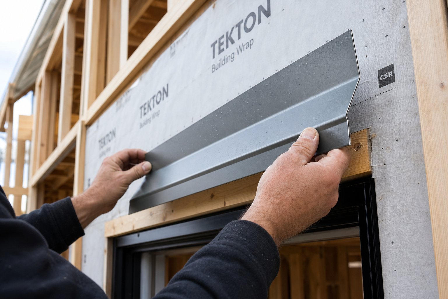
- Position the formed flashing above the window frame with the back leg flat against the sheathing. The drip edge should project outward, past the face of the cladding below.
- Fasten through the top edge of the back leg only — never through the face or drip edge. Use stainless steel or aluminium screws to avoid galvanic corrosion. Space fasteners at 300 mm centres maximum.
- Apply a bead of compatible flashing sealant along the top edge of the back leg where it meets the sheathing, creating a secondary seal line.
A critical point on fastening: every screw or nail through the drip face creates a hole that water can track through via capillary action. Fasteners belong in the back leg — the zone that will be covered and sealed by the WRB lap. If you are learning how to put flashing on a window for the first time, this single rule eliminates one of the most common installation errors.
Integrating the WRB Over the Top Leg
This step is where window installation flashing succeeds or fails. The water-resistive barrier must lap over the top of the back leg — never tuck behind it or terminate at the same height. This overlap is what connects the wall drainage plane to the flashing surface, ensuring water running down the face of the WRB transitions smoothly onto the flashing and out through the drip edge.
The WRB must always lap over the top leg of the head flashing. Reversing this detail — tucking the WRB behind the flashing — directs water straight into the rough opening and is the single most common cause of head flashing failure in Australian residential construction.
Fold the WRB down over the back leg with a minimum 75 mm overlap. Tape the WRB to the face of the back leg using a compatible flashing tape, pressing firmly to ensure full adhesion. If the WRB was slit to allow flashing installation, tape the slit closed above the overlap so no water can enter above the junction. The finished detail should read like roof tiles from top to bottom: WRB overlaps flashing, flashing overlaps window frame, water sheds outward at every transition.
The window flashing how to question ultimately comes down to respecting this layering sequence. Every professional installer and every manufacturer detail converges on the same principle — shingle-lap from top to bottom, with no reverse laps anywhere in the assembly. Installing window flashing correctly at the head takes perhaps 30 minutes per opening once you have the technique down. Repairing the damage from getting it wrong takes weeks and costs thousands — a reality covered next, because recognising failure early is as important as preventing it in the first place.
Common Failure Modes and How to Diagnose Them
A head flashing failure rarely announces itself dramatically. Water enters slowly, saturates timber framing over months or years, and only becomes visible inside the home once significant damage has already occurred. Catching the warning signs early — and understanding what causes them — separates a $300 repair from a $5,000 remediation job involving cladding removal, framing replacement, and mould treatment.
Signs Your Head Flashing Has Failed
The symptoms show up in predictable locations. Because flashing above window openings manages water at the top of the frame, failures tend to produce moisture damage at or above the window head on the interior, and paint or cladding deterioration on the exterior directly around the head junction.
- Water staining on interior plasterboard or trim above the window: Likely cause — reverse WRB lapping. Water running down the building wrap drains behind the flashing rather than over it, enters the rough opening at the head, and wicks along the timber frame until it saturates the plasterboard.
- Bubbling, peeling, or discoloured paint on exterior cladding around the window head: Likely cause — missing or collapsed end dams. Water running along the flashing face reaches the ends, spills sideways into the wall cavity, and saturates the back of the cladding from inside out.
- Mould growth or musty odour at the window-to-wall junction: Likely cause — insufficient back leg height combined with high water volume. During heavy rain, water overshoots the top edge of the flashing and enters the cavity above it. Persistent dampness without drying creates ideal mould conditions.
- Soft or spongy timber reveals or window trim: Likely cause — prolonged failure from any of the above mechanisms. The timber framing has been saturated long enough to begin rotting, indicating the problem has existed for months or years before detection.
- Efflorescence (white mineral deposits) on brickwork directly below the window head: Likely cause — water entering the cavity through failed flashing over window openings, migrating through the mortar, and depositing dissolved salts on the brick face as it evaporates.
These symptoms often mimic window seal failure. Homeowners frequently replace windows or re-caulk repeatedly without realising the flashing behind the frame is the actual source of the leak. If moisture appears at the top of a window — rather than the sill or corners — head flashing is the prime suspect.
Diagnosing the Root Cause Without Destructive Testing
Confirming a head flashing failure does not always require ripping off cladding. Several non-invasive approaches narrow down the problem before committing to a full investigation:
Controlled water testing. Using a garden hose, apply water to the wall above the window in a systematic pattern — start low, move higher. If leaking begins only when water is applied at or above the flashing line, the failure is localised to the head detail. If leaking occurs when water hits the wall well above the window, the WRB or cladding joints higher up may be contributing.
Moisture meter readings. A pin-type or non-invasive moisture meter pressed against the interior plasterboard or timber trim around the window head reveals elevated moisture levels long before visible staining appears. Readings above 20% in timber framing indicate active wetting. Mapping the moisture pattern — higher at one end versus the other — can reveal whether end dams or the central span have failed.
Thermal imaging. An infrared camera shows temperature differentials caused by evaporating moisture in the wall cavity. Wet areas read cooler than surrounding dry material. This approach identifies the extent of moisture spread without any penetration of the wall surface.
When these methods confirm water entry at the window head but cannot pinpoint the exact failure mechanism — or when mould is suspected inside the cavity — professional assessment becomes necessary. A building inspector or remediation specialist can remove a small section of cladding above the window to visually confirm the flashing condition, WRB integration, and timber framing integrity.
Can failed head flashing be repaired in place? Rarely. Because the flashing sits behind the cladding and beneath the WRB, accessing it for repair means removing the cladding course or render above the window and stripping back the WRB lap. At that point, the most cost-effective approach is to replace window flashing entirely rather than attempting to patch a failed component in position. The exception is homes with accessible lap siding — removing a single weatherboard course above the head may expose enough of the flashing to confirm its condition and, if the failure is minor (a single collapsed end dam, for example), carry out a targeted repair without broader demolition.
Knowing how to properly flash a window prevents these failures entirely. But for existing homes where damage is already underway, early diagnosis limits the remediation scope. The longer moisture moves unchecked through a wall cavity, the further it spreads from the original failure point — and the more expensive properly flashing a window becomes when the surrounding framing needs replacing along with the flashing itself.

Choosing Aluminium Windows Built for Flashing Integration
Flashing can only perform as well as the window frame it protects. A perfectly formed piece of aluminium, installed with textbook WRB lapping and sealed end dams, still relies on the window frame head profile to complete the drainage path. If the frame design creates gaps, ledges, or incompatible geometry at the head, water finds its way in regardless of how good the flashing work is above it. The relationship between aluminium flashing for windows and the window frame itself is a system — one component cannot compensate for the other’s shortcomings.
Why Window Frame Design Affects Flashing Performance
The window frame head is the horizontal extrusion at the top of the frame where flashing terminates. On a well-designed aluminium window, this profile does more than simply close off the top of the glass — it actively participates in moisture management. Quality frames include subtle features that most homeowners never notice but that make an enormous difference during aluminium windows installation and over the life of the building:
- Integrated drainage channels: Small grooves or slots machined into the head extrusion capture any condensation or wind-driven moisture that reaches the frame top and direct it to weep outlets at the ends. This prevents pooling where the flashing drip edge meets the frame.
- Compatible flashing rebates: A step or notch in the head profile provides a defined landing zone for the rigid flashing drip edge. Rather than sitting loosely on top of the frame, the flashing tucks into this rebate, creating a positive overlap that resists wind uplift and prevents water from tracking backward via capillary action.
- Clear manufacturer flashing details: Reputable window manufacturers publish installation guides that specify exactly how their frames integrate with standard flashing profiles — including the required overlap, sealant placement, and WRB termination. Frames designed without this documentation leave installers guessing, and guesswork at the window frame head is where failures begin.
- Thermal break continuity at the head: Thermally broken aluminium frames maintain insulation through the head extrusion, preventing the condensation that forms when cold metal bridges warm interior air. Less condensation at the head means less moisture load on the flashing system overall.
Cheaper or poorly engineered frames often feature flat, featureless head profiles with no drainage provision and no defined flashing interface. The installer is left to improvise — relying on sealant to bridge gaps that should not exist, or bending custom returns into the flashing to accommodate a frame that was never designed with window aluminum flashing integration in mind. Every improvisation introduces a potential failure point.
Selecting Aluminium Windows Engineered for Proper Flashing
The easiest way to guarantee clean flashing integration is to choose window systems that were designed for it from the start. Frames engineered for Australian construction practices account for the wall assembly depths, cladding types, and weather exposure levels common across the country. They ship with flashing compatibility built into the extrusion geometry rather than relying on aftermarket solutions.
When evaluating aluminium windows for a new build or renovation, look for these indicators of flashing-compatible design:
- Published installation details showing flashing overlap dimensions and WRB integration at the head
- Head profiles with formed drainage channels and weep slots
- Compatibility testing with standard aluminium flashing gauges (0.5–0.7 mm)
- Compliance with AS 2047 for water penetration resistance — a standard that inherently validates how well the frame performs when flashed correctly
- Options for integrated drip caps on frames destined for high-exposure installations
Frames that meet these criteria simplify the entire installation chain. The builder spends less time improvising, the flashing sits where it should without custom modification, and the completed assembly drains predictably for decades. It is a case where spending more upfront on quality aluminium windows eliminates the downstream cost of flashing failures, cladding removal, and timber remediation.
For homeowners and builders sourcing aluminium window systems designed around Australian flashing practices, MEICHEN’s aluminium window range offers frames engineered with compatible head profiles and clear integration details suited to common Australian cladding systems — from brick veneer to weatherboard and rendered construction. It is worth exploring as a starting point when flashing compatibility and long-term performance are priorities alongside aesthetics and thermal efficiency.
The broader lesson is straightforward: aluminium flashing windows protect best when flashing and frame are treated as a unified system rather than separate trades working independently. Choose the frame with flashing in mind, and the head detail takes care of itself.
Frequently Asked Questions About Aluminium Window Head Flashing
1. What is the purpose of head flashing on a window?
Head flashing is a formed metal component installed directly above the window frame that intercepts water running down the exterior wall and redirects it outward, away from the rough opening. Without it, water follows surface tension into the gap between the window frame and surrounding framing, leading to timber rot, mould growth, and structural damage inside the wall cavity. In Australian conditions with coastal rainfall and wind-driven rain, head flashing is the most critical component in the three-part window flashing system because it handles the highest water volume of any location around the opening.
2. How thick should aluminium head flashing be?
The correct gauge depends on the window width and site exposure. For standard openings up to 900 mm, 0.5 mm aluminium is adequate. Windows between 900 mm and 1500 mm perform better with 0.6 mm or 0.7 mm material to prevent sagging and oil-canning. Openings wider than 1500 mm — large picture windows or stacking sliders — require 0.7 mm to 0.8 mm stock. Thinner material flexes under wind load and loses the positive slope needed to drain water outward, while heavier gauge holds its profile reliably across wider spans.
3. Does the WRB go over or under the head flashing?
The water-resistive barrier (building wrap) must always lap over the top leg of the head flashing, never tuck behind it. This follows the shingle-lap principle where every upper layer overlaps the one below, so water draining down the WRB face transitions smoothly onto the flashing surface and exits through the drip edge. Reversing this detail is the single most common installation error in Australian residential builds and sends water directly into the rough opening, bypassing the flashing entirely.
4. Do I need one or two layers of head flashing?
One properly installed layer of rigid aluminium head flashing with correct WRB integration satisfies Australian building code requirements for most residential applications. A second layer — typically self-adhesive membrane beneath the rigid aluminium — adds worthwhile redundancy in high-risk situations: coastal sites with intense wind-driven rain, multi-storey buildings where upper walls concentrate water onto lower windows, deeply recessed openings in thick brick veneer walls, and cyclone-rated areas in northern Australia where sustained wind pressure forces water past single-layer systems.
5. How can I tell if my window head flashing has failed?
Common signs include water staining on interior plasterboard above the window, bubbling or peeling exterior paint around the window head, mould growth or musty odours at the window-to-wall junction, and soft or spongy timber reveals. On brick veneer homes, white mineral deposits (efflorescence) below the window head also indicate cavity moisture from flashing failure. Non-destructive diagnosis methods include controlled hose testing from low to high on the wall, moisture meter readings on interior surfaces, and thermal imaging to map wet zones within the cavity.
More Window & Door Guides