Understanding Aluminium Door and Window Fabrication
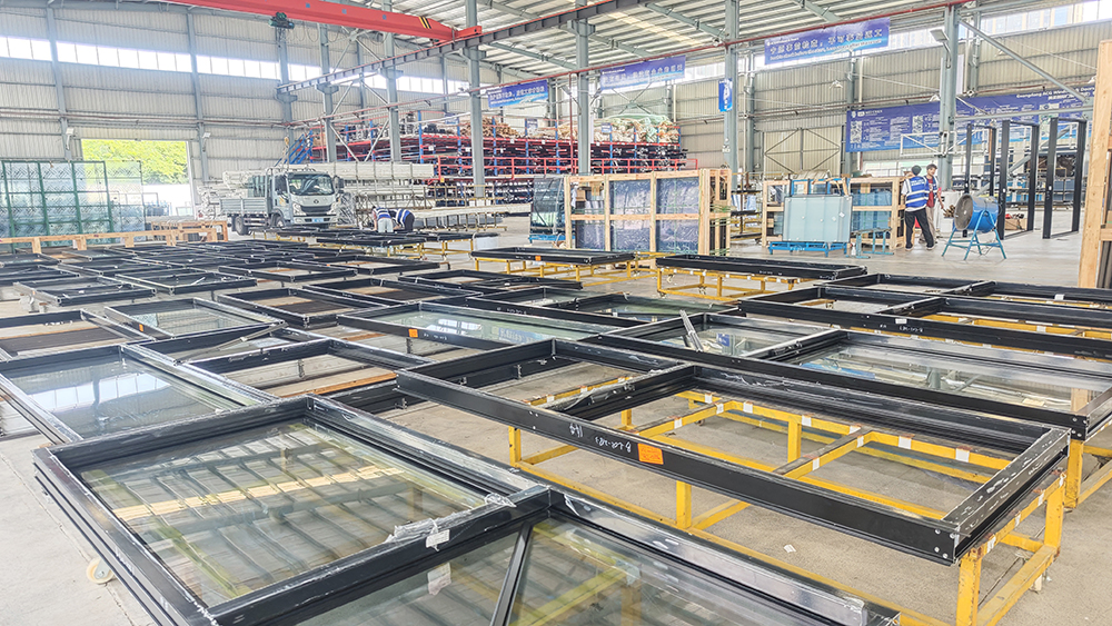
Ever wondered how is a window made from raw aluminium? The answer splits into two very different worlds. One involves molten metal and industrial presses. The other involves precision saws, corner crimps, and careful glazing on a workshop floor. This guide lives firmly in the second world — the hands-on fabrication process that transforms pre-made aluminium profiles into finished, functioning doors and windows ready for installation.
Profile Manufacturing vs. Workshop Fabrication
Aluminium extrusion and aluminium fabrication are related but distinct processes. Extrusion happens at a smelter or mill, where heated aluminium billets are forced through shaped dies at temperatures between 375°C and 500°C to produce profiles with specific cross-sections — frames, sashes, mullions, and tracks. That step creates the raw material.
Fabrication is everything that happens after those profiles arrive at your workshop. It covers cutting profiles to size, machining drainage slots and lock pockets, joining corners mechanically, fitting glass and gaskets, installing hardware, and running quality checks. A fabricator assembles windows and doors from pre-manufactured components, while a full supply chain manufacturer controls the process from profile design through to finished product. This guide focuses on the fabrication side — the practical aluminium joinery work that turns lengths of extruded profile into a complete aluminium door window unit.
Who This Guide Is For
Whether you run a small custom workshop producing bespoke residential pieces or you are exploring production-scale aluminium door window manufacturing for commercial projects, the core fabrication sequence remains the same. The difference is tooling speed, automation level, and batch size — not the fundamental steps themselves.
Here is what this guide covers from start to finish:
- Selecting the right aluminium profile system for your project
- Setting up workshop equipment and safety requirements
- Precision cutting and secondary machining operations
- Frame assembly and corner joining methods
- Glazing panels and installing weather seals
- Fitting hardware for each door and window type
- Running quality control checks and troubleshooting defects
- Choosing between custom fabrication and engineered system solutions
Each phase builds on the last, and getting one step wrong compounds through every stage that follows. The logical starting point sits upstream of any saw cut — it begins with choosing the right profile system for the job.
Step 1. Select the Right Aluminium Profile System
Every fabrication decision downstream — your saw angles, machining operations, corner joining method, even the gaskets you stock — traces back to one choice made before a single profile gets cut. That choice is the profile system itself. Picking the wrong system for the application means reworking frames, ordering incompatible hardware, or delivering aluminium windows doors that fail performance testing. Getting it right here saves time, money, and callbacks.
Thermal Break vs. Non-Thermal Break Profiles
The structural difference is straightforward. A non-thermal break profile is a single piece of extruded aluminium — lightweight, strong, and simple to fabricate. The trade-off is that aluminium conducts heat efficiently, which means the frame becomes a thermal bridge between inside and outside air. In mild climates or non-conditioned spaces like carports and sheds, that is perfectly acceptable.
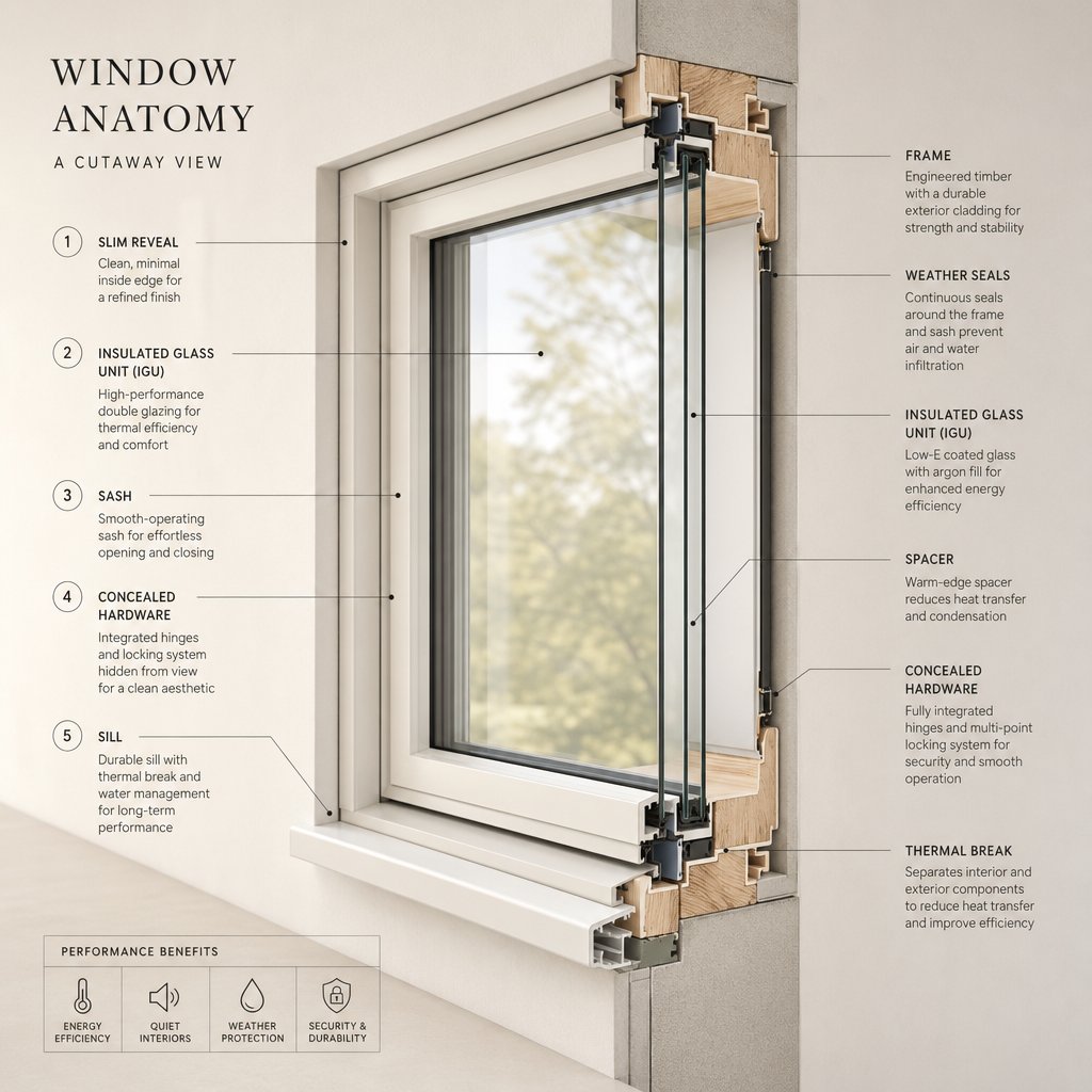
A thermally broken profile splits the frame into two separate aluminium sections connected by a polyamide (nylon) strip. This barrier breaks the conductive path, dramatically reducing heat transfer. The result is better insulation, reduced condensation on interior surfaces, and improved acoustic performance — all factors that matter in Australian residential builds where NCC energy efficiency requirements and NatHERS ratings drive specification choices.
For fabricators, thermal break systems add complexity. You are working with a composite section rather than a solid extrusion, which affects crimping pressure settings and requires care during machining to avoid damaging the polyamide insert. Tooling setup takes longer, but the performance gains justify it for any conditioned living space — particularly in climate zones with hot summers and cold winters like Melbourne, Canberra, or the NSW tablelands.
Matching Profile Systems to Window and Door Types
Profile geometry is not universal. A sliding window needs multi-track rail profiles with smooth-running channels, while a casement window demands profiles engineered for airtight compression seals and hinge screw channels. Bi-fold doors require heavy-duty reinforced sections with integrated pivot and carrier hardware tracks that standard window profiles simply cannot accommodate.
An aluminium windows factory producing multiple product types will stock several profile series — each designed for a specific opening type. Even in a smaller workshop, understanding which profile cross-section suits which window door aluminium application prevents costly mismatches during assembly.
| Profile System Type | Thermal Performance | Typical Frame Width | Fabrication Complexity | Typical Applications |
|---|---|---|---|---|
| Non-Thermal Break | Low (single aluminium section) | 45–55 mm | Low — simple cutting and crimping | Sheds, carports, commercial shopfronts, mild climate zones |
| Thermal Break | High (polyamide barrier) | 55–75 mm | Medium — composite section requires adjusted crimping and careful machining | Residential homes, conditioned spaces, NCC-compliant builds |
| Ultra-Slim | Varies (available in both) | 20–35 mm visible sightline | High — tight tolerances, specialised hardware channels | Architectural feature windows, maximised glass area, modern facades |
Your system choice also dictates minimum wall thickness. Coastal Australian projects exposed to salt air typically specify 6063-T5 alloy at 1.4–1.6 mm wall thickness for corrosion resistance and structural integrity, while standard inland residential work can use profiles down to 1.2 mm. High-rise or cyclone-rated applications in northern Queensland and the NT push that requirement even higher, with reinforced chambers and thicker sections to meet wind load calculations under AS 2047.
Lock in your profile system, confirm it matches your intended window and door types, and verify your workshop tooling can handle the section geometry. Only then does it make sense to start measuring cut lists and firing up the saw.
Step 2. Set Up Your Workshop and Essential Equipment
A profile system sitting in a rack is just raw material until the right machinery turns it into a finished frame. The gap between a competent aluminium window maker and a struggling one often comes down to workshop setup — having the correct machines in the correct sequence, properly maintained, and safely operated. You do not need a million-dollar production line to start, but you do need to understand what each piece of equipment contributes to the fabrication chain.
Core Machinery and What Each Tool Does
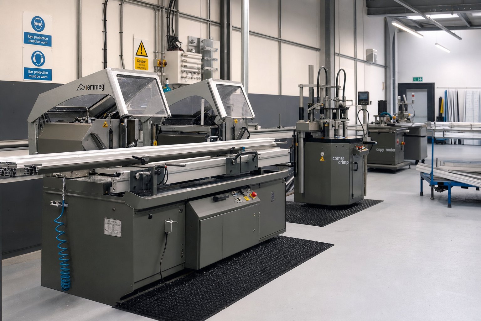
Aluminium door window fabricators rely on a relatively compact set of specialised machines. Each one handles a distinct operation, and skipping any of them forces manual workarounds that compromise accuracy and slow production.
Double-head cutting saw. This is the workhorse. Two saw blades mounted on adjustable heads cut both ends of a profile simultaneously at precise mitre angles — typically 45 degrees for frame corners. A double-head saw eliminates the cumulative error that comes from repositioning a profile between cuts. For batch work, adjustable length stops ensure every piece in a run matches exactly.
Copy router. This machine uses a template-guided spindle to mill specific shapes into the profile — drainage weep slots, espagnolette lock pockets, keep plate recesses, and ventilation openings. The template ensures every routed feature lands in the identical position across hundreds of profiles, which is critical for hardware alignment during assembly.
End milling machine. Before corner cleats can be inserted, the internal walls (tenons) of the profile at each joint must be removed to create a clean cavity. The end mill cuts these internal webs flush, allowing the corner cleat to seat fully inside the profile. Without this step, crimped joints will not close properly.
Corner crimping machine. Once profiles are cut and end-milled, the crimping machine presses corner cleats into the profile cavities using hydraulic force, locking two profiles together at a 90-degree joint. This creates the rigid frame without welding or visible fasteners. Crimping pressure must be calibrated to the profile wall thickness — too little and the joint is loose, too much and the aluminium deforms.
Rubber gasket roller. Glazing gaskets need to be pressed firmly into their channels to create a watertight seal around the glass. A gasket roller applies consistent pressure along the full length of the channel, seating the rubber without stretching or distorting it. Hand-pressing gaskets works on short runs but produces inconsistent compression over longer spans.
Beyond these five core machines, most workshops also keep a pneumatic punch press for hardware screw holes, a portable deburring tool for cleaning cut edges, and basic hand tools — measuring tapes, squares, spirit levels, and rubber mallets for final adjustments.
The table below maps each machine to its function and gives a rough sense of investment level across different scales of aluminum door and window manufacturing:
| Equipment | Primary Function | Budget Tier |
|---|---|---|
| Single-head cutting saw (manual) | Mitre cuts — one end at a time | Entry (~$3,000–$6,000 AUD) |
| Double-head cutting saw (semi-auto) | Simultaneous mitre cuts on both ends | Mid (~$15,000–$35,000 AUD) |
| Double-head cutting saw (CNC) | Automated length and angle adjustment, batch cutting | Production (~$50,000–$120,000 AUD) |
| Copy router (manual template) | Drainage slots, lock pockets, keep recesses | Entry (~$2,500–$5,000 AUD) |
| Copy router (CNC) | Programmable multi-pattern routing | Production (~$30,000–$70,000 AUD) |
| End milling machine | Removes internal tenons for corner cleat insertion | Entry/Mid (~$3,000–$10,000 AUD) |
| Corner crimping machine (single-head) | Presses corner cleats into one joint at a time | Entry (~$4,000–$8,000 AUD) |
| Corner crimping machine (four-head) | Crimps all four corners simultaneously | Production (~$40,000–$90,000 AUD) |
| Rubber gasket roller | Seats glazing gaskets into profile channels | Entry (~$200–$600 AUD) |
| Pneumatic punch press | Punches screw holes for hardware mounting | Entry/Mid (~$2,000–$5,000 AUD) |
A small custom workshop can get operational with entry-level manual equipment for roughly $15,000–$30,000 AUD. A mid-scale operation producing 20–50 units per week typically invests $80,000–$150,000 AUD in semi-automated gear. Full CNC production lines capable of high-volume output push well beyond $250,000 AUD — but they also slash labour costs and cycle times dramatically.
Workshop Safety and PPE Requirements
Aluminium fabrication generates sharp swarf, fine metallic dust, and significant noise. Freshly cut profile edges can slice skin as easily as a blade, and high-speed saw operation demands respect. Every person on the workshop floor needs appropriate personal protective equipment — no exceptions.
Mandatory PPE includes:
- Cut-resistant gloves — essential when handling raw-cut profiles and sharp offcuts. Look for EN 388 rated gloves with at least Level C cut protection.
- Safety glasses or face shields — aluminium chips eject at speed during cutting and routing. Polycarbonate lenses with side shields are the minimum standard.
- Hearing protection — double-head saws and crimping machines generate noise levels above 85 dB(A). Earmuffs or moulded earplugs are required for prolonged exposure.
- Steel-capped boots — profiles are heavy and awkward. A 6-metre length sliding off a rack can cause serious foot injuries.
- Dust extraction system — aluminium swarf and fine particles must be captured at the source. A properly ducted extraction system connected to each saw and router protects lungs and keeps the workspace clean.
Beyond personal gear, workshop layout matters. Position machines in fabrication sequence — cutting saw first, then end mill, copy router, crimping station, and finally a glazing bench — so profiles flow through the space without backtracking. Keep glass storage racks separate from machining areas to prevent accidental damage from flying swarf. Ensure adequate ventilation, clearly marked emergency stops on every machine, and unobstructed access to fire extinguishers.
With the right equipment bolted down and safety protocols in place, the real precision work begins — translating cut lists into accurately machined profiles ready for assembly.
Step 3. Cut and Machine the Aluminium Profiles
Precision lives or dies at the saw. Every millimetre of error introduced during cutting compounds through assembly, glazing, and hardware fitting — a 1 mm deviation on a single mitre becomes a 2 mm gap at the corner joint, which then throws gasket compression off and invites water ingress. This phase of aluminium windows fabrication demands the most attention to measurement discipline and machine setup of any step in the entire process.
Precision Cutting and Mitre Angles
Cutting begins with a cut list — a detailed schedule derived from your window or door drawings that specifies every profile length, its mitre angle, and which machining operations it needs before assembly. Double-check the cut list against the opening dimensions, accounting for frame clearances (typically 10 mm per side for installation tolerance) and any mullion or transom intersections that alter individual member lengths.
For standard frame fabrication, profiles are cut at 45-degree mitres so two pieces meet to form a clean 90-degree corner. This is the dominant method for casement windows, awning windows, and hinged door frames. Sliding window and door frames, by contrast, often use 90-degree square cuts with mechanical screw-fixed joints, since the track profiles do not lend themselves to mitred corners.
Setting up your saw correctly makes the difference between tight joints and visible gaps. On a double-head saw, lock both heads to exactly 45 degrees using a calibrated angle gauge — do not rely on the machine’s printed scale alone, as these drift over time. Set length stops for batch consistency so every piece in a run comes out identical. When cutting multiple frames of the same size, this eliminates the creeping variation that manual measurement introduces piece by piece.
Common mistakes at this stage include blade deflection from dull teeth, which causes uneven mitres that look fine on one face but are angled on the other. As cutting accuracy research highlights, feed rate matters too — pushing profiles through too aggressively heats the aluminium, creates burrs, and pulls the workpiece off-line. Start with a slower feed and let each tooth do its work cleanly. Clamp both ends of the profile firmly before every cut. Loose ends vibrate, scratch the freshly cut surface, and can kick the offcut into the blade.
A purpose-built aluminium cutting saw with a carbide-tipped blade designed for non-ferrous metals delivers the cleanest results — burr-free faces that need no secondary finishing. Standard wood blades can technically cut aluminium, but they dull quickly and leave rougher edges that compromise gasket seating later.
Machining Operations Explained
Cutting gives you profiles at the correct length and angle. Machining adds the functional features that allow those profiles to accept hardware, drain water, and join together structurally. Each operation targets a specific need, and the sequence matters — performing them out of order risks damaging already-completed features or losing datum references.
Here is the correct machining sequence for a typical frame or sash profile:
- End milling — Remove the internal walls (tenons) at each end of the profile to create a clear cavity for corner cleats. The end mill cuts these webs flush to the required depth, usually 30–50 mm depending on cleat length. Skip this step and the cleat cannot seat fully, resulting in a weak or misaligned corner joint.
- Copy routing for drainage — Mill weep holes and pressure-equalisation slots into the bottom rail of the frame. These small rectangular openings (typically 5 mm x 20 mm) allow any water that enters the glazing rebate to drain to the exterior. Position them at intervals specified by the profile system — usually one slot per 600 mm of frame width, plus one near each corner.
- Copy routing for lock pockets — Cut recesses into the sash profile to house the espagnolette lock gearbox and face plate. The template ensures the pocket depth and width match the lock body precisely, so the mechanism sits flush and operates without binding.
- Slot milling for keep plates — Machine shallow recesses into the frame profile where strike plates and keeps will be mounted. These slots allow the hardware to sit flush with the profile surface rather than protruding, which would interfere with sash closure.
- Punching for hardware screw holes — Use a pneumatic punch press to create pilot holes for hinge screws, lock fixing screws, and friction stay mounting points. Punching is preferred over drilling for thin-wall aluminium because it produces a cleaner hole without the risk of the drill bit grabbing and distorting the profile wall.
Not every profile needs every operation. A fixed-lite frame requires only end milling and drainage routing — no lock pockets, no hinge holes. A sliding sash needs roller mounting slots instead of friction stay holes. Match your machining schedule to the window or door type, and mark each profile clearly so nothing gets missed or doubled up on the workshop floor.
Dimensional accuracy across all these operations is non-negotiable. A lock pocket routed 2 mm too high means the handle sits crooked and the locking points do not engage the keeps. A weep hole drilled into the wrong chamber means water drains internally instead of externally. Use calibrated templates, check the first piece in every batch against the hardware it needs to accept, and measure twice before committing the router to the profile. The few seconds spent verifying position save hours of rework at the assembly bench.
With profiles cut to length and fully machined, they are ready to become frames — which means corner cleats, crimping pressure, and the critical squareness checks that determine whether everything downstream fits as it should.
Step 4. Assemble Frames and Join Corners
Machined profiles lying on a bench are just components. The assembly phase is where they become a structural unit — and where the strength and longevity of the finished aluminum door window gets locked in. A poorly joined corner will flex under wind load, allow water past the seal, and eventually work itself loose. A well-crimped corner holds rigid for decades. The difference comes down to technique, machine calibration, and a willingness to verify squareness before moving on.
Corner Crimping and Mechanical Joints
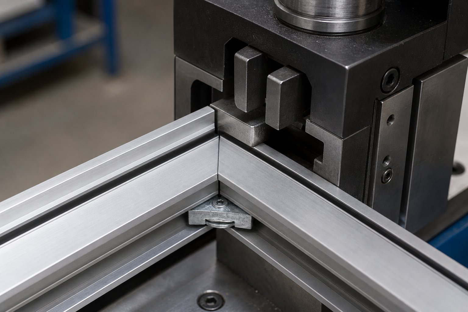
The dominant corner joining method in aluminium door window manufacturing is mechanical crimping. It produces a tight, permanent joint without visible fasteners, welding, or adhesive curing time. The process relies on corner cleats — small die-cast or extruded aluminium keys shaped to fit inside the profile cavity — that get pressed into place under hydraulic force.
Here is how the crimping sequence works in practice:
1. Apply sealant to the corner cleat. Before insertion, run a bead of section adhesive or weather-resistant corner sealant along the cleat faces. This serves two purposes: it lubricates insertion and, once cured, creates a moisture barrier inside the joint cavity. Some fabricators also apply sealant to the mitre faces themselves for additional weather protection.
2. Insert the cleat into the first profile. Slide the corner cleat halfway into the end-milled cavity of one profile. It should seat fully against the internal walls without force — if it binds, the end milling was insufficient and needs recutting. The cleat must sit flush with the mitre face so the two profiles meet without a gap.
3. Bring the second profile onto the cleat. Align the mitre faces and push the second profile onto the exposed half of the cleat. The two 45-degree cuts should meet tightly with no visible gap along the external face. Any daylight between the mitres indicates a cutting angle error that needs correcting before crimping — once crimped, the joint cannot be adjusted.
4. Position the assembly in the crimping machine. Place the joined corner into the machine’s clamping jaws, ensuring both profiles sit flat and square against the machine bed. The crimping dies must align with the cleat position inside the profile — typically marked by a guide line on the machine or measured from the corner point.
5. Crimp. Activate the hydraulic press. The dies punch inward on both sides of each profile simultaneously, deforming the aluminium wall into the cleat’s locking grooves. This mechanical interlock is what gives the joint its strength. As industry documentation on corner assembly notes, a properly crimped joint forms seamlessly and resists water ingress and cracking far better than screw-fixed alternatives.
6. Verify the joint. Check that the crimp marks are even on both sides, the mitre faces remain flush, and no profile distortion has occurred. Run a fingertip across the external corner — you should feel a smooth transition with no step or lip between the two profiles.
For a standard rectangular window frame, repeat this process at all four corners. A single-head crimping machine handles one corner at a time, requiring you to rotate the frame between operations. A four-head machine crimps all corners simultaneously, which is faster and eliminates the risk of accumulated misalignment from sequential crimping.
Squareness verification is the final and most critical check. Measure both diagonals of the assembled frame corner-to-corner. If the two measurements match within 1 mm, the frame is square. A difference greater than 1.5 mm means one or more corners are out — usually caused by uneven crimping pressure or a mitre angle that was slightly off 45 degrees. Catching this here is essential. An out-of-square frame will not accept glass properly, hardware will bind, and the unit will fight the opening during installation.
Door Frame Assembly and Reinforcement
Door fabrication follows the same crimping principles but introduces additional structural demands that window frames rarely face. A standard hinged door frame might stand 2,100 mm tall or more, carry a heavy glass panel, and endure thousands of opening cycles per year. That loading profile changes the assembly approach in several ways.
Heavier profiles and steel reinforcement. Door frame profiles are typically deeper and thicker-walled than window sections — 60 mm to 100 mm face width is common. For tall or wide openings, steel reinforcement bars are inserted into the profile’s internal chambers before assembly. These galvanised steel sections add rigidity and prevent the aluminium from deflecting under the weight of the door leaf or wind pressure. The reinforcement must be cut slightly shorter than the profile to avoid interfering with corner cleat insertion.
Screw-fixed corners. While crimping works well for standard door frames, heavier commercial doors and bi-fold systems often use screw-fixed corner joints instead. This method uses heavy-duty corner brackets secured with stainless steel screws through pre-punched holes. It allows for on-site assembly of large frames that cannot be transported as a single unit, and it provides a serviceable joint that can be tightened if the frame is subjected to repeated impact loading.
Multi-point lock rail integration. Hinged doors with multi-point locking systems require a lock rail — a reinforced vertical section within the door leaf that houses the lock gearbox, shootbolts, and hook locks. This rail must be positioned precisely during sash assembly so the locking points align with their corresponding keeps on the frame. Misalignment of even 2–3 mm means the lock will not engage fully, compromising security and weather sealing.
Hinge reinforcement plates. Standard aluminium wall thickness is not sufficient to hold hinge screws under the repeated stress of a swinging door. Steel or stainless steel reinforcement plates are fixed inside the profile at each hinge position before the frame is crimped. These plates distribute the load across a wider area and prevent the screw threads from stripping out of the softer aluminium over time.
Sash assembly for both windows and doors follows the same crimping or screw-fixing logic as the outer frame, but with tighter tolerances. The sash must fit within the frame with consistent clearance gaps — typically 3–4 mm per side — to allow smooth operation while maintaining seal compression. Measure the sash against the frame before glazing to confirm fit.
Before moving to the glazing bench, run through this checklist of common assembly mistakes and their prevention:
- Out-of-square frames — caused by uneven crimping pressure or inaccurate mitre cuts. Prevent by verifying diagonal measurements immediately after crimping and rechecking after the frame is moved to the next station.
- Insufficient crimping pressure — results in loose corners that flex under load. Prevent by calibrating the crimping machine to the specific profile wall thickness and testing joint rigidity by hand before proceeding.
- Misaligned drainage channels — occurs when profiles are rotated incorrectly during assembly, placing weep holes on the interior face or blocking them against the corner cleat. Prevent by marking the drainage side of each profile clearly during machining and confirming orientation before crimping.
- Corner cleat not fully seated — happens when end milling depth is insufficient or swarf remains in the cavity. Prevent by blowing out cavities with compressed air before cleat insertion and checking that the cleat slides in without resistance.
- Sealant squeeze-out on visible faces — caused by over-applying corner adhesive. Prevent by using a controlled bead and wiping excess immediately after crimping, before it cures.
A frame that passes squareness checks and feels solid at every corner is ready for its most visible component — the glass. Glazing demands its own set of techniques for gasket placement, packer positioning, and drainage integrity, where the quality of your assembly work either pays off or gets exposed.
Step 5. Glaze the Panels and Install Weather Seals
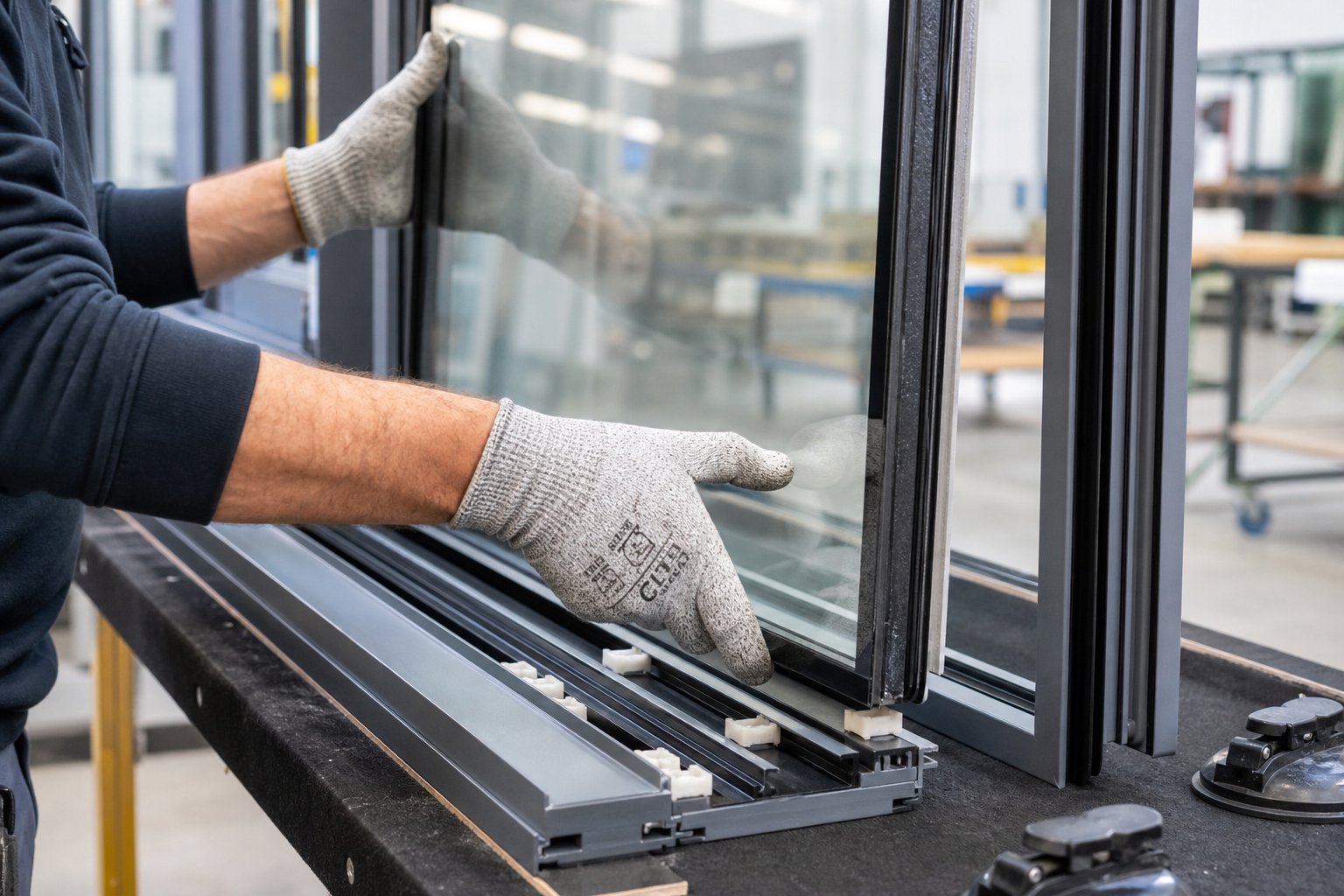
A perfectly square, solidly crimped frame means nothing if water gets past the glass. Glazing is where fabrication meets weatherproofing — and it is the phase most responsible for long-term performance complaints when done poorly. The goal is not simply to hold glass in place. It is to create a managed system where seals keep air and water out, packers distribute weight correctly, and drainage channels route any moisture that does penetrate safely back to the exterior.
Gasket Installation and Glass Setting
Aluminium window and door systems use two distinct gasket types, each with a specific job. Confusing their roles or installing them in the wrong channel is one of the fastest paths to seal failure.
Wedge gaskets (also called glazing beads or snap-in gaskets) sit in the channel that holds the glass pane against the frame. Their cross-section is typically a tapered wedge shape that compresses as the glazing bead is clipped into place, locking the glass firmly without direct metal-to-glass contact. These gaskets must run continuously around the full perimeter of the glass — any gap or short section creates a point where water can bypass the seal and enter the glazing rebate.
Bubble gaskets (or weather seals) sit on the sash-to-frame interface. Their hollow tubular cross-section compresses when the window or door closes, forming an airtight barrier against wind and rain. These seals are responsible for the unit’s air permeability rating and contribute significantly to acoustic insulation. They need to be seated firmly in their channel using a gasket roller — hand-pressing tends to leave sections under-compressed, particularly around corners where the gasket must negotiate a 90-degree turn without bunching or pulling away from the channel walls.
When rolling gaskets into their channels, work from one corner continuously around the frame rather than starting from the middle of a run. At corners, use a small dab of gasket adhesive to prevent the rubber from retracting over time as it relaxes. Never stretch the gasket during installation — stretched rubber shrinks back and opens gaps at the joints.
Glass setting follows gasket preparation. This is where glazing packers become critical. These small plastic shims sit between the glass edge and the frame, serving two purposes: they prevent glass-to-metal contact (which causes stress cracks) and they transfer the weight of the glass unit to specific load-bearing points on the frame.
Correct packer placement depends on the window type:
- Fixed windows — place setting blocks (packers) at the bottom rail, approximately 100 mm from each corner. These carry the full dead weight of the glass. Side packers at the same 100 mm offset prevent lateral movement.
- Side-hung casement windows — the bottom packer on the hinge side and the top packer on the lock side carry the diagonal load. This “toe and heel” arrangement prevents the sash from dropping over time as the weight transfers through the glass to the frame.
- Top-hung awning windows — packers sit at the top rail (hinge side) with diagonal support at the lower corners to resist the opening weight.
For single-glazed applications, a 4–6 mm glass pane is relatively light and forgiving. Double-glazed insulated glass units (IGUs) change the equation significantly. A standard IGU with two panes of 4 mm glass and a 12 mm spacer weighs roughly 20 kg per square metre — a 1,200 mm x 1,500 mm unit tips the scales at around 36 kg. That weight demands precise packer positioning and adequate packer thickness (typically 5–6 mm for the setting blocks) to avoid point-loading the sealed unit’s edge spacer, which can crack the perimeter seal and cause the IGU to fog internally over time.
Handle IGUs with care during installation. Never slide them across the frame — lift and place. The edge seal is the unit’s moisture barrier, and dragging it across an aluminium lip can nick or compress the sealant, leading to premature failure. Use suction cups for units larger than 1 m² to maintain control and avoid twisting the glass.
Once the glass is set on its packers, clip the glazing bead into place, pressing the wedge gasket firmly against the glass face. Work from one corner around the perimeter, ensuring the bead snaps fully home along its entire length. Any section that sits proud indicates the gasket is bunched underneath — pull it back, reseat the gasket, and try again.
Weather Sealing and Drainage Systems
Sealing a window against weather is not about making it hermetically closed. A well-designed aluminium frame manages water through a staged system — deflecting most rain at the outer seal, neutralising pressure differentials in a drainage cavity, and routing any residual moisture safely outward before it reaches the interior seal.
This principle is called pressure-equalised drainage. It works on a simple piece of physics: water is driven through gaps not just by gravity, but by pressure differences between the exterior and interior of the frame. If wind creates higher pressure outside than inside the drainage cavity, water gets forced inward through any micro-gap. Pressure equalisation vents connect the drainage cavity to the exterior atmosphere, allowing pressures to balance. Once equalised, the driving force disappears and water simply drains downward under gravity.
In practical fabrication terms, this means your drainage system needs three elements working together:
Weep holes. These are the slots you routed during the machining phase — typically 5 mm x 20 mm openings in the bottom rail of the outer frame. They must exit on the exterior face only, positioned at the lowest point of the glazing rebate so water cannot pond. Standard spacing is one weep slot per 600 mm of frame width, with additional slots near each corner where water naturally collects. On sliding window tracks, weep holes sit in the outer track channel where rainwater accumulates behind the sash.
Pressure-equalisation vents. These small openings (often just 3–4 mm diameter holes) connect the drainage cavity to the outside air without allowing bulk water entry. They are typically positioned higher than the weep holes — at the sides or top of the frame — so water does not flow back through them. Some profile systems incorporate these vents into the extrusion design itself, while others require the fabricator to drill them at specified locations.
Brush seals and pile weatherstrips. On sliding windows and doors, the sash-to-frame interface cannot use compression gaskets because the sash needs to slide freely. Instead, brush pile strips (fine nylon bristles set in a woven backing) are pressed into channels along the sliding tracks. These strips allow smooth sash movement while blocking wind-driven rain and reducing air infiltration. They also prevent insects and dust from entering. Replace brush pile that has been flattened or worn — it loses its sealing capacity quickly once the bristles no longer spring back.
Critical rule: drainage must always exit on the exterior face of the frame. Never allow sealant, packers, or debris to block weep holes or drainage slots. A blocked weep hole turns the glazing rebate into a reservoir — water builds up, overwhelms the inner seal, and leaks into the building interior. During final assembly, visually confirm every drainage path is clear before the unit leaves the workshop.
Silicone sealant has a role in this system, but a limited one. Apply a small bead of neutral-cure silicone at internal corner junctions where gaskets cannot form a continuous seal — typically where horizontal and vertical gaskets meet at frame corners. Do not run silicone across weep holes or along the bottom of the glazing rebate. Silicone in the wrong place creates a dam that traps water exactly where you need it to flow freely.
For coastal Australian projects where salt-laden wind drives rain horizontally into frames, drainage performance becomes even more critical. Specify stainless steel or plastic weep covers (small flap valves over the exterior weep slots) that allow water out but resist wind-driven spray from entering. In cyclone-rated applications across northern Queensland and the NT, the entire drainage system must be validated against the higher pressure differentials generated by extreme wind events — standard weep spacing may need to be increased, and additional pressure-equalisation vents added to cope with the load.
With glass set, gaskets seated, and drainage confirmed clear, the frame is weatherproof — but it cannot yet open, close, or lock. Hardware installation transforms a sealed panel into a functioning window or door, and each product type demands its own specific fittings, adjustment sequences, and alignment checks.
Step 6. Install Hardware for Each Door and Window Type
Hardware is what separates a glazed panel from a functioning product. Every window and door type demands a distinct combination of operating mechanisms, locking systems, and adjustment points — and each one introduces its own fabrication quirks. Getting hardware right means smooth operation on day one and reliable performance years down the track. Getting it wrong means callbacks, binding mechanisms, and security failures that no amount of adjustment can fully resolve.
Hardware for Windows — Casement, Sliding, and Awning
Casement and awning windows rely on two primary hardware components: friction stays and espagnolette locks. The friction stay is the hinge mechanism that controls how far the sash opens and holds it at any position without slamming shut or drifting open. As installation guidance from hardware specialists notes, friction stays mount to the upper and lower edges of the sash, typically 100–150 mm from the corners. The fixed arm attaches to the frame, the sliding arm to the sash. Correct positioning is critical — too close to the corner and the stay interferes with the gasket; too far inward and the sash does not open to its full designed angle.
After mounting, test the sash through its full range of motion. Use a spirit level to confirm the sash sits horizontal when closed, and check that the gap between sash and frame remains uniform on all sides. Uneven gaps indicate the stay is misaligned or the screws need adjustment. Friction tension should hold the sash open at 90 degrees without creeping — if it drifts, the stay is undersized for the sash weight.
The espagnolette lock sits on the opposite stile to the hinges. Its gearbox drops into the routed pocket you machined earlier, with the faceplate sitting flush against the profile surface. When the handle turns, shootbolts extend from the top and bottom of the gearbox into keeps mounted on the frame head and sill. Alignment between the shootbolts and keeps must be precise — 2 mm of misregistration and the lock will not fully engage, leaving the window insecure and the compression seal under-loaded.
Sliding windows use a completely different hardware set. Instead of hinges and locks, they run on rollers and secure with interlocking snib locks. Rollers mount into the bottom rail of the sliding sash — typically two per sash, positioned roughly 50 mm from each end. Each roller has a height adjustment screw accessible from the sash face, allowing you to fine-tune the sash height until it runs smoothly along the track without dragging or rattling. Set the rollers so the sash interlocks engage cleanly with their keeps on the fixed panel, and confirm the sash cannot be lifted out of the track from the exterior — an anti-lift block at the head rail prevents this.
Hardware for Doors — Hinged, Sliding, and Bi-Fold
Hinged doors carry significantly more weight than windows, which changes the hardware specification entirely. Butt hinges or flag hinges rated for the door leaf weight (typically 60–120 kg for a standard residential unit) mount into reinforced sections of the frame. Three hinges are standard for doors up to 2,100 mm tall; four hinges for anything taller or heavier. Each hinge position must align with the steel reinforcement plates installed during frame assembly — screwing into unreinforced aluminium alone will strip under repeated use.
Multi-point locking systems are standard on hinged aluminium doors. The lock rail houses a central gearbox operated by a lever handle, with hook locks and shootbolts extending to engage keeps at the head, sill, and intermediate points along the frame. During installation, close the door leaf into the frame and mark the exact keep positions by operating the lock and noting where each bolt contacts the frame. Rout or chisel the keep recesses at these marked positions — never transfer measurements from a drawing without physical verification, because frame assembly tolerances can shift keep locations by several millimetres from the theoretical position.
Threshold drainage integration is a detail unique to doors. The door sill must allow water to drain outward while the threshold seal compresses against the door bottom to block wind-driven rain. Adjustable drop seals or compression bulb seals on the door leaf bottom work in conjunction with a ramped sill profile that channels water toward the exterior weep slots. Confirm the seal compresses evenly across the full sill width when the door is closed — high spots cause air leaks, low spots allow water past.
Sliding doors scale up the roller and track system used in sliding windows. Heavy-duty tandem roller carriages — often with stainless steel bearings rated for 100 kg or more per panel — mount into the door sash bottom rail. Track profiles are deeper and wider than window tracks to handle the increased load. Adjustment follows the same principle as sliding windows: set roller height until the door glides freely, interlocks engage, and the anti-lift system prevents the panel from being removed externally.
Bi-fold doors introduce the most complex hardware of any aluminium door type. Each panel connects to the next via pivot hinges, and the entire assembly rides on a top-hung or bottom-rolling carrier system along a head track or sill track. Top-hung systems suspend the panels from roller carriages running in an overhead rail, with a bottom guide channel keeping the panels aligned. Bottom-rolling systems place the weight on floor-level track rollers with a top guide. Each pivot point must be shimmed and adjusted so panels fold flat against each other without binding, and the carrier rollers must be set so the stack clears the opening jamb cleanly.
The table below maps each product type to its specific hardware, fabrication requirements, and the fitting challenges you are most likely to encounter:
| Window/Door Type | Key Hardware | Unique Fabrication Steps | Common Fitting Challenges |
|---|---|---|---|
| Casement window | Friction stays, espagnolette lock, shootbolts | Route lock pocket, punch hinge screw holes, machine keep recesses | Shootbolt-to-keep misalignment; friction stay undersized for sash weight |
| Awning window | Friction stays (top-mounted), chain winder or lever operator | Route winder mechanism recess, reinforce top rail for stay load | Chain winder cable tension; sash dropping if stays lose friction |
| Sliding window | Tandem rollers, interlocking snib, anti-lift block | Machine roller housing slots in sash bottom rail, install brush pile in tracks | Roller height inconsistency causing dragging; worn brush pile allowing air leakage |
| Hinged door | Heavy-duty hinges, multi-point lock, drop seal | Install steel reinforcement at hinge points, route lock rail, fit adjustable threshold | Keep alignment across multiple locking points; hinge sag on heavy panels |
| Sliding door | Heavy-duty tandem carriages, flush lock, anti-lift system | Machine deep roller housing, install heavy-gauge track, fit interlock hardware | Panel weight causing track wear; flush lock engagement with thick profiles |
| Bi-fold door | Pivot hinges, roller carriages, top/bottom guides, flush bolts | Drill pivot pin housings, install carrier track, fit panel-to-panel hinges and seals | Panel stack alignment; carrier roller adjustment for smooth folding; pivot wear over time |
Regardless of product type, every piece of hardware should be cycled through its full operation at least ten times on the bench before the unit ships. Open, close, lock, unlock — feel for binding, listen for scraping, and watch for any movement that suggests a fastener is not holding. Hardware that operates stiffly in the workshop will only get worse once installed in an opening under real-world load. Catching adjustment issues here, while the unit is still accessible on a flat bench, takes minutes. Fixing them on a scaffold or ladder after installation takes hours.
Smooth hardware operation confirms the fabrication work is sound — but it does not confirm the unit will perform under pressure, literally. The final phase subjects the finished product to dimensional checks, water testing, and function cycling that either validate your workmanship or reveal defects while they can still be corrected in-house.
Step 7. Run Quality Checks and Troubleshoot Defects
A unit that looks good on the bench can still fail in the field. Quality control is not a single inspection at the end of the line — it is a series of checkpoints woven through every fabrication phase, each one designed to catch errors before they get buried under the next layer of work. Skipping these checks is how workshops end up with water-damaged plasterboard, warranty claims, and a reputation that takes years to rebuild.
Quality Control Checkpoints Throughout Fabrication
Effective QC follows the fabrication sequence. Each checkpoint targets the specific failure modes introduced at that stage, catching problems while correction is still quick and cheap.
Post-cut measurement. Immediately after cutting, verify every profile length against the cut list using a calibrated tape or digital calliper. Check mitre angles with a precision square — both faces of the cut should meet the blade at exactly 45 degrees. A factory QC analysis confirms that even a 1–2 mm deviation at cutting causes assembly gaps, poor sealing, and installation problems downstream. Reject any piece outside tolerance rather than hoping it will close up during crimping. It will not.
Post-assembly squareness. After crimping, measure both diagonals of the frame. Equal diagonals (within 1 mm) confirm the frame is square. Also check that all four corners are flush on the external face — run a straight edge across each joint to detect any step or lip. Verify corner joint rigidity by gripping opposite corners and applying moderate racking force. A properly crimped frame should feel completely rigid with zero flex.
Post-glazing seal test. Once glass is set and gaskets installed, perform a water spray test. Using a garden hose with a spray nozzle set to a fine mist, direct water at the external face of the glazed unit for at least 15 minutes while the frame sits upright at a slight angle. Inspect the interior face and glazing rebate for any moisture penetration. As sealing performance research notes, water penetration testing under controlled pressure is one of the most reliable indicators of real-world weatherproofing — it exposes gasket gaps, blocked drainage, and packer misplacement that visual inspection alone cannot detect.
Post-hardware function test. Cycle every piece of hardware through its full operation a minimum of ten times. Open and close the sash, engage and disengage all locking points, and test friction stays at multiple opening angles. Listen for scraping, feel for binding, and confirm that locks engage their keeps without excessive force. For sliding units, run the sash back and forth checking for smooth travel, consistent roller contact, and secure interlock engagement at the closed position.
Final visual inspection. Before protective wrapping, examine every visible surface for scratches, dents, sealant smears, and swarf contamination. Check that all drainage weep holes are clear and unobstructed. Confirm protective film is intact on surfaces that will be exposed during transport and installation. Label each unit with its opening reference and orientation to prevent site installation errors.
Common Mistakes and How to Fix Them
Certain fabrication errors appear repeatedly across workshops of every size. Knowing their root causes lets you prevent them systematically rather than chasing symptoms unit by unit.
| Defect | Root Cause | Prevention | Correction (If Already Occurred) |
|---|---|---|---|
| Visible gap at mitre joint | Blade deflection from dull teeth, incorrect angle setting, or profile not clamped firmly during cut | Replace blades on schedule, verify angle with precision square before each batch, clamp both ends of profile securely | If gap is under 0.5 mm, fill with colour-matched aluminium putty. Over 0.5 mm — recut the profile; filler will crack under thermal movement |
| Weak or loose corner joint | Insufficient crimping pressure, undersized corner cleat, or incomplete end milling leaving material blocking cleat insertion | Calibrate crimping machine to profile wall thickness, confirm cleat slides freely into cavity before crimping, blow out swarf with compressed air | Disassemble the corner if possible and re-crimp with correct pressure. If the profile is already deformed from the first attempt, the piece must be scrapped and recut |
| Water ingress through bottom rail | Blocked weep holes (sealant overspill, debris, or packer sitting over the drainage slot), or weep holes drilled into the wrong chamber | Visually confirm every weep slot is clear after glazing, never apply sealant near drainage paths, mark drainage chambers clearly during machining | Remove glazing bead, clear the blockage, and re-test with water spray. If weep holes are in the wrong chamber, new drainage slots must be routed in the correct position |
| Cracked or fogged IGU (insulated glass unit) | Incorrect packer placement causing point-loading on the edge seal, or glass slid across the frame during installation rather than lifted and placed | Follow toe-and-heel packer positioning for each window type, use suction cups for units over 1 m², never drag glass across aluminium | The IGU must be replaced — once the perimeter seal is compromised, moisture ingress is irreversible. Correct packer positions before re-glazing |
| Hardware binding or not engaging | Lock pocket routed in wrong position, keep recesses misaligned with shootbolts, or frame out of square causing sash-to-frame gap variation | Check first machined piece against actual hardware before batch routing, mark keep positions from the physical sash rather than drawings alone, verify frame squareness before fitting hardware | Re-rout the pocket or keep recess to the correct position. If the frame is out of square, the frame itself must be corrected first — shimming hardware to compensate for a racked frame creates ongoing operational problems |
| Air leakage at sash perimeter | Bubble gasket not fully seated in channel, gasket stretched during installation and retracted at corners, or gasket cross-section incompatible with the gap dimension | Use a gasket roller for consistent compression, work from one corner continuously without stretching, confirm gasket size matches the profile channel | Remove and reseat the gasket. If it has been stretched and is now too short, replace with a fresh length cut slightly long and compressed into the channel |
A pattern runs through most of these defects: they originate upstream but only become visible downstream. A dull blade causes a bad cut, which causes a gapped corner, which causes a seal failure, which causes a water leak on site six months later. The cheapest fix is always prevention at the source — sharp tooling, calibrated machines, and verification at every phase transition.
For workshops producing volume, tracking defect rates by type and station reveals where your process is weakest. If 80% of your rework traces back to cutting errors, the solution is not better sealant — it is blade maintenance and operator training at the saw. That kind of systematic thinking separates a fabrication operation that improves over time from one that keeps solving the same problems on repeat.
With quality verified and defects resolved, the finished units are ready to leave the workshop. But for fabricators weighing whether to continue building every frame from scratch or transition toward pre-engineered aluminium systems, the next consideration is understanding where custom fabrication makes sense — and where a system-based approach delivers better performance with less risk.

Step 8. Move from Fabrication Knowledge to Project-Ready Systems
Building aluminium doors and windows from individual profiles, cleats, and gaskets gives you complete control over every dimension and detail. For one-off custom pieces — an unusually shaped fixed lite, an oversized pivot door, or a heritage replacement that no catalogue system accommodates — that hands-on fabrication approach is irreplaceable. But control comes with responsibility. Every performance outcome rests entirely on your machining accuracy, gasket selection, drainage design, and hardware integration. There is no system-level testing certificate backing up the finished unit.
Larger residential builds, multi-storey projects, and commercial applications shift the equation. When you need dozens of openings that must all meet verified ratings for air permeability, water tightness, and structural wind load under AS 2047, fabricating each unit from first principles introduces risk that engineered system solutions are specifically designed to eliminate.
When to Fabricate Custom vs. Use Engineered Systems
The decision is not binary — many workshops do both, choosing custom fabrication for bespoke elements and system-based production for standard openings within the same project. The key factors that tip the balance are project scale, performance certification requirements, and available workshop capacity.
Custom fabrication makes sense when:
- The opening geometry is non-standard and no existing system profile accommodates it
- You are producing a small number of units (one to five) where system minimum order quantities are impractical
- The project demands a specific aesthetic — unusual frame proportions, non-standard finishes, or integration with existing heritage details
- You have full control over installation and can manage performance outcomes through workmanship alone
Engineered systems deliver better outcomes when:
- The project requires certified performance data — wind load ratings, water tightness classifications, and thermal performance values verified through independent laboratory testing
- You are producing volume (ten or more units) where system consistency reduces QC burden and rework rates
- NCC compliance documentation is required for council approval, particularly in bushfire-prone areas (BAL ratings) or cyclone regions where structural certification is mandatory
- The client expects warranty coverage backed by a system manufacturer, not just the fabricator’s workmanship guarantee
Modern aluminium system solutions are designed as complete packages. The profile extrusions, corner cleats, gasket cross-sections, drainage components, and hardware are all engineered to work together as a tested assembly. A fabricator working within a system follows the manufacturer’s fabrication manual — cut lengths, machining positions, crimping specifications, and hardware locations are all pre-determined and validated. This does not eliminate skill from the process, but it does remove guesswork from critical performance decisions like gasket sizing, drainage spacing, and structural reinforcement requirements.
The performance testing that backs these systems is substantial. As high-performance aluminium system research highlights, engineered systems undergo rigorous classification for air permeability, water tightness under pressure, and wind load resistance — metrics that individual workshop-fabricated units rarely get independently tested against unless the project specifically demands it.
Exploring Aluminium System Categories for Your Project
The range of available system types has expanded significantly beyond the single-profile-fits-all approach of earlier decades. Each category addresses different architectural needs, climate demands, and budget positions — and understanding what exists helps you match the right solution to each project rather than defaulting to custom fabrication for everything.
Key system categories worth exploring include:
- Thermal break window and door systems — polyamide-insulated profiles engineered for energy efficiency in conditioned spaces, meeting NCC Section J requirements and improving NatHERS ratings for residential builds
- Non-thermal break systems — cost-effective single-section profiles suited to mild climates, commercial shopfronts, and non-conditioned enclosures where thermal performance is less critical
- Ultra-slim frame systems — minimised sightlines (as narrow as 20–35 mm visible frame width) that maximise glass area for contemporary architectural designs demanding uninterrupted views
- Facade and curtain wall systems — structural glazing solutions for multi-storey applications, combining weather resistance with large-format panel capacity
- Full-house custom systems — integrated packages covering every opening type in a residential project under a single matched aesthetic, from sliding doors to awning windows to fixed lites
For readers who have followed this fabrication guide and want to explore what project-ready aluminium systems look like in practice, MEICHEN’s product range offers a useful reference point. Their catalogue spans thermal break, non-thermal break, ultra-slim, and facade categories — each designed as a complete system with matched profiles, hardware, and sealing components that simplify fabrication while delivering certified performance for Australian conditions.
Whether you continue fabricating custom units in your own workshop or transition toward system-based production, the fundamentals covered in this guide remain the foundation. Profile selection, precision cutting, accurate machining, solid corner joints, proper glazing technique, correct hardware installation, and rigorous quality control — these steps define the difference between aluminium doors and windows that perform reliably for decades and units that generate callbacks within months. The fabrication knowledge does not become redundant when you adopt a system. It becomes the skill base that lets you execute that system correctly.
Frequently Asked Questions About Aluminium Door and Window Fabrication
1. What equipment do I need to start making aluminium windows and doors?
At minimum, a small workshop needs a double-head cutting saw for precise mitre cuts, a copy router for drainage slots and lock pockets, an end milling machine to prepare profiles for corner cleats, a corner crimping machine to join frames, and a rubber gasket roller for glazing seals. Entry-level manual equipment starts around $15,000–$30,000 AUD, while semi-automated setups for mid-scale production typically require $80,000–$150,000 AUD. Full CNC production lines exceed $250,000 AUD but dramatically reduce labour costs and cycle times.
2. What is the difference between thermal break and non-thermal break aluminium profiles?
A non-thermal break profile is a single piece of extruded aluminium — simple to fabricate but conducts heat freely between interior and exterior. A thermal break profile splits the frame into two aluminium sections connected by a polyamide (nylon) strip, which breaks the conductive path and significantly reduces heat transfer. Thermal break systems offer better insulation, reduced condensation, and improved acoustic performance, making them essential for conditioned living spaces in Australia. They add fabrication complexity due to the composite section requiring adjusted crimping pressure and careful machining to avoid damaging the polyamide insert.
3. How do you join the corners of an aluminium window frame?
The primary method is mechanical crimping. Corner cleats — small die-cast aluminium keys — are inserted into end-milled cavities at each profile joint, then pressed into place using a hydraulic crimping machine. The dies punch inward on both sides of each profile, deforming the aluminium wall into the cleat’s locking grooves to create a permanent mechanical interlock. Before crimping, sealant is applied to the cleat for moisture protection. After crimping, squareness is verified by measuring both diagonals of the frame — they must match within 1 mm. Heavier door frames may use screw-fixed corner brackets instead for serviceability.
4. Why do aluminium windows leak water and how can I prevent it?
Water ingress typically results from blocked weep holes, incorrectly positioned drainage slots, or poorly seated gaskets. Prevention starts during fabrication: route weep holes into the correct exterior-facing chamber of the bottom rail at intervals of one per 600 mm of frame width, ensure pressure-equalisation vents are positioned higher than weep holes, and confirm all drainage paths remain clear after glazing. Never apply silicone sealant near drainage slots. After assembly, perform a water spray test for at least 15 minutes to verify seal integrity before the unit leaves the workshop.
5. Should I fabricate custom aluminium windows or use an engineered profile system?
Custom fabrication suits non-standard geometries, small quantities (one to five units), and bespoke aesthetic requirements where you control installation quality. Engineered systems are better for projects requiring certified performance data (wind load, water tightness, thermal ratings under AS 2047), volume production of ten or more units, NCC compliance documentation, or manufacturer-backed warranty coverage. Many workshops combine both approaches — custom fabrication for unique elements and system-based production for standard openings. Systems like those offered by MEICHEN provide matched profiles, hardware, and gaskets tested as a complete assembly, reducing QC burden while delivering verified performance for Australian conditions.
More Window & Door Guides