What Is an Aluminium Window Frame Section Detail
Picture a window frame sliced cleanly in half, like cutting through a piece of fruit to reveal the seeds, chambers, and layers hidden beneath the skin. That cross-sectional slice, drawn to scale on paper or screen, is an aluminium window frame section detail. It exposes everything you cannot see once the window is installed: the internal geometry of the extrusion, the position of seals and thermal barriers, drainage pathways, and exactly how glass sits within the frame.
Unlike a simple elevation drawing that shows what a window looks like from the outside, or a 3D render designed to sell an aesthetic, a section detail drawing communicates how the frame actually works. It is a technical document that carries more performance information per square centimetre than any brochure or specification sheet. Architects rely on them during design documentation. Builders reference them for accurate installation. Engineers use them to verify structural adequacy and compliance. Homeowners reviewing quotes can use them to understand precisely what they are paying for.
What a Section Detail Actually Shows
A section drawing, as Fontan Architecture explains, is created from a vertical plane that slices through the subject to reveal what lies within. Applied to an aluminium window profile, this means the drawing cuts perpendicular to the frame length, exposing the hollow chambers inside the extrusion, the depth of the glazing pocket, the exact location of weatherstrips, and the relationship between the fixed frame and any operable sash.
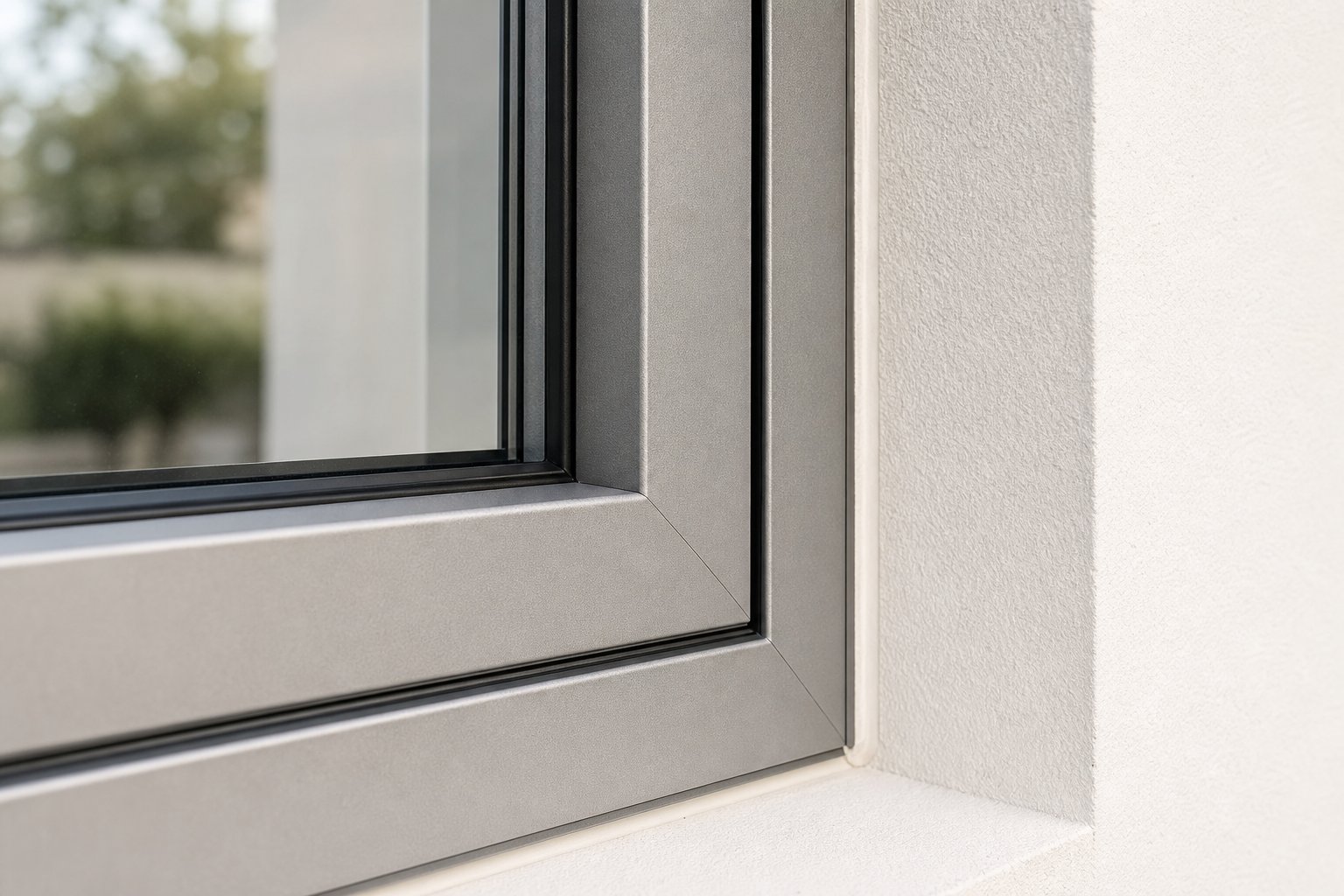
Where elevation views flatten a window into a rectangle, the aluminium window profile section view peels back that simplicity. You see wall thickness of the aluminium, thermal break positioning, gasket compression zones, and how the frame interfaces with surrounding construction, whether that is brick veneer, lightweight cladding, or rendered blockwork. Every line on the drawing represents a physical edge, a material boundary, or an assembly interface.
Why Section Details Matter for Every Stakeholder
Different people read the same drawing for different reasons. For architects, section details confirm that a specified system meets NCC requirements for thermal performance, weather resistance, and structural adequacy under AS 2047. The window frame cross section explained in a supplier’s technical documentation becomes the basis for compliance verification.
For builders, these drawings translate directly into installation accuracy. They reveal how much clearance to leave in the structural opening, where packers sit, how flashings integrate, and what sealant joints are required. Getting this wrong by even a few millimetres can compromise weatherproofing or void warranties.
For homeowners comparing quotes from different suppliers, learning how to read an aluminium window section detail turns an opaque technical process into something transparent. You can compare frame depths, glazing capacities, and seal configurations side by side rather than relying solely on marketing language.
In window specification, the section detail is the single most information-dense document available. Every line, hatching pattern, and dimension annotation encodes a decision about performance, durability, and buildability.
This guide walks through each element of these technical drawings systematically, building your ability to interpret any aluminium window frame section detail you encounter, regardless of the system or supplier. The vocabulary alone opens a different kind of conversation with professionals, one grounded in shared technical understanding rather than assumption.
Essential Terminology in Section Detail Drawings
Every component visible in an aluminium window frame section detail has a specific name, a defined function, and a measurable dimension. Knowing these terms transforms an abstract technical drawing into a readable map. Without this vocabulary, you are essentially looking at shapes. With it, you understand exactly what each shape does, how it interacts with adjacent parts, and why it matters for the window’s long-term performance.
The terminology below covers what you will encounter in virtually any aluminium window section detail, from a basic fixed lite to a complex tilt-and-turn system. Think of this as your decoder ring for the drawings that follow in supplier documentation and architectural specifications.
Frame and Sash Profile Terminology
Three measurements define the basic geometry of any aluminium window profile, and they appear on nearly every section detail you will encounter.
Frame depth is the total profile dimension measured from the exterior face to the interior face of the frame. In a section drawing, this is usually the horizontal measurement running from left to right (or top to bottom, depending on orientation). A residential casement might have a frame depth of 44 mm to 72 mm, while commercial systems often exceed 100 mm for structural reasons. This single number tells you a great deal about structural capacity and thermal performance potential.
Sightline describes the visible width of the frame as seen from the interior once the window is installed. It is the portion of the frame not concealed by the wall reveal or covered by glazing beads. The CN Glass glossary refers to a related concept as “sight size,” the actual opening that admits daylight. In a section detail, sightline is the distance between the inner edge of the glass and the inner face of the frame profile. Narrower sightlines maximise glass area and daylight, which is why slimline systems are popular in contemporary Australian homes.
Rebate depth is the channel within the frame or sash that receives the glass or panel. The rebate forms an angled pocket, and its depth determines the maximum glass thickness the frame can accommodate. A shallow rebate might handle only single glazing, while a deeper rebate suits double-glazed insulating glass units (IGUs) of 20 mm or more. In section detail drawings, the rebate is typically the stepped recess where you see the glass edge sitting.
Additional frame-related terms you will encounter include:
- Mullion — a vertical framing member that divides a window into separate lites or panels. In section details, a mullion appears as a standalone profile connecting two adjacent glazed openings.
- Transom — the horizontal equivalent of a mullion. It divides upper and lower window sections and often carries the weight of the glass above it.
- Jamb — the vertical side members of the outer frame. Section details through the jamb show how the frame interfaces with the wall structure.
- Sash — the operable or fixed inner frame that holds the glass. Section details reveal how the sash nests within or overlaps the outer frame, and where hardware engagement points sit.
- Sub-sill — a secondary sill profile fixed beneath the main window sill, often used to manage drainage away from the wall below or to provide a mounting platform when the window sits on a masonry or timber substrate.
Sealing and Weather Protection Components
Australian conditions demand robust weatherproofing, whether that is wind-driven rain in coastal Melbourne, cyclone-grade pressure in northern Queensland, or persistent dust in inland regions. Section details reveal exactly how a frame resists the elements, and the sealing components are where performance lives or fails.
Weatherstripping refers to compressible strips of resilient material seated in dedicated channels within the frame and sash profiles. Their job, as Pro Aluminium’s glossary notes, is to seal the sash-to-frame junction against air and water infiltration. In a section drawing, you will see these as small shapes (often circular or bulb-shaped) sitting in narrow slots machined into the aluminium.
There are distinct seal types visible in section details:
- Compression seals — rubber or EPDM gaskets that compress when the sash closes against the frame, forming a tight barrier. They appear as solid or hollow bulb profiles in the section view.
- Brush seals — fine bristle strips used primarily in sliding window systems where a compression seal would create too much friction. In section drawings, they show as a hatched rectangular block with a fin-like profile.
- Fin seals — flexible rubber fins that deflect on contact, commonly used as secondary seals or in sliding track systems alongside brush seals.
The weather bar is a raised aluminium or rubber ridge at the sill that water must climb over before it can penetrate the frame junction. In section details, it appears as a small protrusion rising from the sill profile, positioned between the outer face and the first line of weatherstripping. Its height and position directly affect the frame’s resistance to water ingress under wind pressure.
Glazing System Elements
The glazing pocket is where glass meets frame, and section details show this interface with precision. Understanding these components clarifies whether a frame can handle the glass configuration your project requires.
Glazing pocket refers to the full cavity formed by the rebate on one side and the glazing bead on the other, into which the glass unit sits. Its width determines maximum glass thickness. A pocket of 24 mm, for example, can typically accept a standard double-glazed unit (4 mm glass + 12 mm spacer + 4 mm glass = 20 mm) with room for gaskets and tolerance.
Glazing beads are the strips that lock the glass into the rebate. In section details, they appear as the removable profile element on the interior side of the glass. Two main types exist:
- Snap-in beads — clip into place using integral lugs that engage with channels in the frame. Quick to install and remove for reglazing. Shown in sections as a profile with a protruding clip feature.
- Screw-fixed beads — mechanically fastened for higher security or in applications where snap-in retention is insufficient (large or heavy glass panels). Shown with a visible screw line in the section.
Setting blocks are small pads of neoprene or similar material placed at the base of the glazing pocket to support the glass weight and maintain correct positioning. In section detail views, they appear as small rectangles sitting on the rebate platform beneath the glass edge.
Glazing gaskets (sometimes called wedge gaskets or pressure plates) sit between the glass face and the bead or rebate, cushioning the glass and providing the final weather seal at the glazing interface.
Finally, drainage slots — also called weep holes — are small openings in the sill section that allow any water reaching the glazing pocket to escape to the exterior. In section details, they appear as breaks or notches in the outer rebate wall, sometimes with baffled covers to prevent wind-driven water from re-entering. Their presence (or absence) in a drawing tells you immediately whether the system relies on drained or face-sealed weatherproofing principles.
Collectively, these window section detail component names form the language of performance specification. Each term corresponds to a line, a shape, or a dimension on the drawing. With this vocabulary in place, interpreting how those components work together as a system becomes a matter of reading spatial relationships rather than guessing at abstract geometry.
How to Read Any Window Section Detail Systematically
Knowing the vocabulary is one thing. Knowing where to look first, and what to look for in sequence, is what turns a jumble of lines into a coherent story about how a window performs. Every aluminium window frame section detail follows the same fundamental logic: it represents a physical slice through materials that transition from outdoor exposure to indoor comfort. Reading it in that same direction, exterior to interior, gives you a repeatable method that works regardless of the system, the supplier, or the drawing style.
The approach below works whether you are reviewing a residential casement detail from a local fabricator or a commercial curtain wall section in a DA submission. Treat it as a universal reading sequence.
Reading from Exterior to Interior
Most section detail drawings follow a consistent orientation convention. The exterior face of the frame sits on the left side of the drawing (or at the top, for horizontal sections through a sill or head). The interior face sits on the right (or bottom). Some drawings label this explicitly with “EXT” and “INT” markers, but many assume you recognise the convention. A quick clue: the side with exposed weather seals, drainage slots, and a more complex outer profile is always the exterior.
Working from outside in, you pass through four distinct zones in sequence:
- Outer weathering surface — the aluminium face exposed to rain, UV, and salt air. Look for the powder-coated or anodised outer skin and any projecting weather bars or drip edges designed to shed water away from joints.
- Drainage plane — the zone where weep slots, pressure equalisation chambers, and condensation channels sit. This is where the frame manages any water that gets past the first line of defence.
- Thermal barrier zone — the polyamide strip or pour-and-debridge section that separates the outer aluminium from the inner aluminium, preventing direct heat conduction through the frame. It typically appears as a narrow band of different material spanning between two halves of the profile.
- Interior finish face — the visible indoor surface of the frame, usually a clean flat or slightly contoured profile with the glazing bead and interior weatherstrip completing the assembly.
This four-zone mental model applies to every thermally broken aluminium profile you will encounter. For non-thermally-broken systems, zones two and three collapse into one, and you will notice the aluminium runs continuously from outside to inside with no material interruption.
Identifying Scale and Dimension Annotations
Scale determines whether the profile you are looking at is life-sized on the page or reduced. Common window section detail scale conventions include 1:1 (full size, used for gasket details and hardware interfaces), 1:2 (half size, common for frame profiles in residential documentation), and 1:5 (used when showing the window within its wall context). A scale bar or ratio notation near the drawing title confirms which applies.
Dimension annotations communicate exact measurements. As First In Architecture explains, dimension lines are drawn lighter than structural elements, offset slightly from the object, and terminated with ticks, arrows, or dots where they cross extension lines. In window section details, you will commonly see dimensions for frame depth, sightline width, glazing pocket width, and overall profile height.
Leader lines are angled lines with an arrowhead pointing to a specific component, connected to a text label or note. They identify individual parts such as “EPDM gasket,” “thermal break,” or “22 mm IGU.” Reference markers, often circles containing a number, link to a legend or separate detail sheet where further information lives. Reading window frame dimension annotations accurately depends on recognising these conventions and tracing each line back to its origin point on the profile.
Recognising Material Hatching Patterns
Hatching is the pattern fill applied within cut surfaces to identify what a material is without needing a label on every single element. Standard hatching styles have been used in construction drawings for decades, and while some variation exists between offices, the core conventions remain stable.
In aluminium window section details, you will encounter these patterns repeatedly:
- Aluminium extrusions — typically shown with tight diagonal hatching lines (45-degree parallel lines at close spacing), or sometimes left as a solid dark fill in simplified drawings.
- Thermal break polyamide — often represented with a distinct cross-hatch pattern or a stippled fill that contrasts clearly with the adjacent aluminium. Some drawings use a solid black fill for the polyamide strip to make it instantly identifiable.
- Rubber gaskets and EPDM seals — usually shown as solid black or very dense fill shapes, reflecting their dark appearance and flexible nature.
- Glass — represented by a single thin line or a very light blue-green tint in coloured drawings. In monochrome sections, glass appears as parallel closely-spaced lines or simply an empty space bounded by gasket profiles.
- Sealant — often shown as a dotted or speckled fill, or occasionally cross-hatched at a different angle to surrounding materials.
When aluminium window hatching patterns are unclear, a legend or key on the drawing sheet will decode them. As with reading floor plans, the principle is consistency: once you identify a hatching style in one area of the drawing, it means the same material everywhere else it appears on that sheet.
Combining these three skills, directional reading, dimension interpretation, and material recognition, gives you a reliable method for how to interpret window section detail drawings from any source. You are no longer dependent on a supplier walking you through their specific product. You can pick up any section detail, orient yourself within seconds, and extract meaningful performance information independently. That literacy becomes particularly powerful when profiles differ significantly between window operation types, where the geometry shifts to accommodate hinges, tracks, and locking mechanisms that each demand their own spatial logic.
How Section Profiles Differ by Window Type
A casement window and a sliding window might look similar from across the room, but slice through their frames and the internal geometry tells two completely different engineering stories. The operation type, how the window opens, closes, and locks, dictates the shape of every chamber, the position of every seal, and the depth of every profile. This is where section details become genuinely powerful: they reveal why a sliding window track section profile looks nothing like a casement, even when both come from the same manufacturer and share the same finish.
Understanding these differences matters practically. If you are comparing quotes for different window types in the same project, the section details explain why frame depths vary, why sightlines change between operable and fixed panels, and why some configurations accommodate thicker glass than others. Each operation type imposes its own mechanical constraints on the aluminium extrusion, and the section detail is where those constraints become visible.
Casement and Awning Frame Sections
Casement windows hinge on one vertical edge and swing outward (or occasionally inward), while awning windows hinge along the top edge and pivot outward at the base. Both share a common sectional characteristic: the sash overlaps the outer frame when closed, compressing weatherstrips at the contact interface. But the hinge side and the lock side of the same window produce noticeably different section profiles.
On the hinge side, the casement window frame section detail shows the sash profile sitting tight against the frame with minimal clearance. The hinge pocket, a flat machined recess or a projecting lug channel, appears as an asymmetric feature on one face of the sash or frame profile. The section here reveals how the sash pivots clear of the frame without binding, typically requiring a stepped or chamfered outer edge that provides rotational clearance.
The lock side tells a different story. Here the section shows the sash overlapping the frame more substantially, with compression seals positioned to engage under the clamping force of the locking mechanism. Multi-point locking systems, now standard on quality Australian casement and awning windows, require the frame profile to include a continuous channel or series of keeper pockets along the lock stile. In section views, these appear as recessed slots within the frame profile where locking hooks or rollers engage. The depth of this channel and its position relative to the weatherstrip line directly affects both security and seal compression.
Awning window section profile dimensions share much of this logic but rotated 90 degrees. The hinge detail appears at the head (top) of the frame, while the locking and primary seal compression occurs at the sill. One distinctive feature of awning sections is the sill drainage arrangement: because the sash swings outward from the bottom, the sill profile must manage water shedding differently than a casement, with weather bars positioned to prevent water tracking back along the sash face when the window is closed.
Both casement and awning sections typically show two or three lines of weatherstripping, creating separate air and water barrier planes. The space between these seal lines forms a pressure equalisation zone visible in the section as a small chamber between the sash and frame profiles.
Sliding Window and Door Track Profiles
Sliding systems produce the most geometrically complex section details because they must accommodate two or more sashes passing across each other on parallel planes. Rather than the overlap-and-compress approach of hinged windows, sliding sections reveal a track-and-roller relationship that demands precise vertical geometry.
The track profile dominates the sill section of any sliding window. Rails, raised ridges machined or extruded into the sill, guide the rollers that carry each sash. Rail height determines how securely the sash sits in its track and affects resistance to lateral wind loads. In section details, you will see the rail as a raised fin with a radiused top surface, and the corresponding roller housing in the sash profile as a cavity sized to contain the wheel assembly. Higher-performance sliding systems use taller rails and deeper roller cavities to resist uplift forces, particularly relevant in Australian cyclone-rated zones.
The meeting stile, where two sliding sashes pass or interlock at the centre of the window, is perhaps the most distinctive element of a sliding window track section profile. This interlocking profile appears in section as two complementary shapes that nest together without touching, with brush seals or fin seals bridging the gap. The interlock geometry prevents the sashes from being separated or lifted out under wind pressure while allowing smooth horizontal travel.
Where a casement section shows one frame-to-sash relationship, a sliding section often reveals three or four parallel planes: the outer sash, the inner sash, and the frame members on each side. The section makes clear how much depth is consumed by this layering. A two-track sliding system typically requires 50 percent or more frame depth compared to an equivalent casement, simply to house the parallel sash planes and the track infrastructure between them.
Brush seals replace compression gaskets in most sliding sections because a compression seal would create excessive friction against lateral sash movement. In the section drawing, these appear as rectangular blocks of fine bristle material seated in channels along the track rails and meeting stiles.
Fixed-Lite and Curtain Wall Sections
Strip away all operating hardware, hinges, tracks, locking mechanisms, and the section detail simplifies dramatically. A fixed lite aluminium frame section detail shows only the outer frame, glazing pocket, glazing bead, and seals. No sash profile exists because the glass sits directly within the main frame, locked in place by beads and gaskets.
This simplicity translates into two practical advantages visible in the section. First, the sightline shrinks because there is no sash overlapping the frame. Where a casement might show 55 to 65 mm of visible frame width from inside, a fixed lite can achieve 35 to 45 mm or less. Second, the glazing pocket can be deeper relative to the overall frame depth because none of that depth is consumed by hardware channels or sash clearances. This often allows fixed panels to accept thicker glass configurations, including heavy acoustic laminated units or triple-glazed IGUs.
Structural glazing sections, common in curtain wall and shopfront applications, take this further. Here the glass is bonded to the frame with structural silicone rather than mechanically retained by beads. In section, the difference is stark: instead of a projecting bead profile on the interior, you see a flat aluminium carrier with a thick band of structural sealant adhesively connecting the glass to the frame. The external appearance shows no visible frame at all, as the glass spans continuously across the facade with only silicone joints between panels.
For residential projects, the practical takeaway is this: where you do not need an openable panel, specifying a fixed lite delivers thinner sightlines and often better structural and thermal performance from a shallower frame. The section detail makes this trade-off measurable rather than theoretical.
| Window Type | Typical Frame Depth | Approximate Sightline | Max Glass Thickness | Key Section Feature |
|---|---|---|---|---|
| Casement | 44–72 mm | 55–65 mm | 24–28 mm | Sash overlap with multi-point lock channel |
| Awning | 44–72 mm | 55–65 mm | 24–28 mm | Top-hung hinge pocket, sill weather bar |
| Sliding (2-track) | 70–130 mm | 40–100 mm per sash | 20–28 mm | Parallel track rails, interlock meeting stile |
| Tilt-and-Turn | 70–82 mm | 60–75 mm | 28–44 mm | Dual-mode hardware groove, deep rebate |
| Fixed Lite | 44–71 mm | 35–45 mm | 28–50 mm | No sash profile, maximised glazing pocket |
| Structural Glazing | 50–100 mm | 0 mm (external) | 28–44 mm | Silicone-bonded glass, no external bead |
Tilt-and-turn windows deserve a brief mention because their section drawings are among the most complex in residential applications. The tilt and turn window section drawing reveals a deep eurogroove channel running around the sash perimeter, housing the multi-function hardware that allows the sash to both tilt inward from the top and swing inward from the side. This hardware channel, typically 16 mm wide and positioned precisely within the sash profile, is the distinguishing mark. The frame depth runs deeper than a standard casement to accommodate the dual-action mechanism, and the rebate depth is generous to handle the thicker glass units these systems commonly carry.
Comparing sections across window types side by side reveals a clear pattern: the more complex the operation, the deeper and wider the profiles become, and the more of the frame depth gets dedicated to hardware and movement clearance rather than thermal performance or glazing capacity. This trade-off sits at the heart of every specification decision, and it is only fully visible when you examine the profiles in cross-section rather than face-on. The thermal implications of these varying geometries, particularly how thermal break depth and position shift between window types, shape energy performance in ways the next section explores.

Thermal Break Technology Revealed in Section Views
Aluminium conducts heat roughly 1,000 times more efficiently than timber. Without intervention, the frame becomes a thermal highway, transferring summer heat inward and winter warmth outward at a rate that undermines even the best glazing. The solution is visible in every thermally broken aluminium window profile drawing: a narrow band of non-metallic material that physically splits the extrusion into two independent halves, one facing the weather, one facing your living space.
This polyamide thermal barrier in the window frame is the single most consequential feature you can identify in a section detail. Its presence, depth, and position tell you more about a frame’s energy performance than almost any other element on the drawing. Yet it occupies only a few millimetres of the profile’s total width. Knowing what to look for, and what it means, separates a genuinely informed specification from a guess.
Identifying Thermal Breaks in Section Drawings
In a standard (non-broken) aluminium section, the extrusion hatching runs continuously from exterior face to interior face. One material, one uninterrupted thermal path. A thermally broken frame, by contrast, shows the aluminium profile clearly divided into two separate pieces joined by a reinforced polyamide strip. This strip appears as a distinct band, typically rendered with a different hatching pattern, solid black fill, or stippled texture that contrasts sharply with the surrounding aluminium.
Look for it in the middle zone of the profile, roughly centred between the outer weathering face and the inner finish face. In a well-drawn aluminium window thermal break section detail, you will see:
- Two aluminium halves (exterior and interior) each with their own chamber geometry and wall thickness
- A connecting barrier, usually 15 to 35 mm deep, made from glass-fibre-reinforced polyamide (PA66) or, in some systems, a polyurethane pour-and-debridge core
- Mechanical interlocking at the junction, visible as knurled or serrated edges where the polyamide grips into grooves in the aluminium
The two manufacturing methods produce slightly different visual signatures in section. A strip-insertion system (the more common approach in Australian residential windows) shows the polyamide as a discrete strip with uniform width, mechanically crimped into channels on each aluminium half. A pour-and-debridge system fills a cavity between the two aluminium sections with liquid polyurethane that cures and is then partially cut away to break the thermal bridge. In section, this appears as an irregular shaped core rather than a uniform strip, often with slightly wider and more organic geometry.
Both approaches achieve the same fundamental goal: creating an insulating barrier within the conductive aluminium that, as IQ Glass explains, separates the frame into two distinct interior and exterior pieces joined with a less conductive material. If you cannot see this separation in a section drawing, the system is not thermally broken, regardless of what marketing language surrounds it.
How Thermal Break Geometry Affects U-Values
The thermal performance of an aluminium frame is expressed as a Uf value (frame U-value), measured in W/m2K. A lower number means less heat transfers through the frame. The thermal break’s geometry directly influences this figure through three measurable characteristics visible in the section detail:
- Break depth — the distance the polyamide spans between the outer and inner aluminium halves. A deeper thermal break creates a longer path that heat must travel through the low-conductivity material. Deeper breaks generally correlate with improved insulation performance.
- Number of chambers — some high-performance systems use multiple parallel polyamide strips or a single strip with internal air chambers. More chambers trap more still air, adding insulative layers. In section drawings, these appear as hollow voids within or adjacent to the thermal break zone.
- Break position relative to the glazing plane — where the thermal break sits in relation to the glass determines whether the frame creates a cold bridge at the glass-to-frame junction. Ideally, the break aligns with the insulating cavity of the glazing unit itself, maintaining a continuous thermal barrier across the full assembly.
A standard non-broken aluminium frame might produce a Uf value several times worse than the same profile with a thermal break installed. The Concept Aluminium guide to thermally broken systems notes that combining an insulated frame with appropriate glazing delivers significantly better overall window performance (Uw value) than either component alone.
This matters in practical terms because the overall thermal performance of a window (the Uw value) is a weighted combination of the glass performance (Ug), the frame performance (Uf), and the edge-of-glass linear thermal transmittance. A high-performing double-glazed unit paired with a non-broken aluminium frame still produces a mediocre overall Uw value. The section detail is where you verify that the frame holds up its end of the thermal equation.
Be cautious of quoted “U-values” that do not specify which metric they represent. A supplier quoting only the Ug value (glass alone) without disclosing the Uf or overall Uw may be obscuring a non-broken or poorly performing frame. The section detail itself is your verification tool: if you cannot see a thermal break in the cross-section, the frame contribution to the overall U-value will be substantially worse than a broken equivalent.
Connecting Thermal Breaks to NCC and WERS Compliance
Under the National Construction Code, residential buildings must meet minimum energy efficiency requirements assessed through tools like NatHERS. Windows play a central role in these calculations because, as AWS Australia reports, up to 49% of heat lost in winter and up to 87% of heat gained in summer can come through the windows. The frame’s thermal performance is a critical variable in these energy models.
For homes targeting higher star ratings (particularly 7 stars and above under NatHERS), thermally broken aluminium frames are increasingly a baseline requirement rather than a premium upgrade. The section detail tells you immediately whether a proposed window system meets this threshold. Look for the polyamide separation. If it is absent, the system is thermally standard, and achieving higher energy ratings becomes dependent on compensating elsewhere in the building envelope, often at greater cost.
The Window Energy Rating Scheme (WERS) provides a standardised way to compare window energy performance across products. WERS ratings factor in both frame and glazing contributions, meaning a thermally broken frame with appropriate glazing will produce materially different heating and cooling star ratings compared to a non-broken system with identical glass. When reviewing section details alongside WERS data, the thermal break geometry you see in the drawing directly correlates with the rating numbers on the label.
For projects in climate zones with extreme temperature differentials, inland NSW towns with hot summers and cold winters, or alpine regions in Victoria, the thermal break depth and position revealed in the section detail become critical specification criteria rather than optional enhancements. The same applies to condensation management: without a thermal break, the interior face of the aluminium frame can drop below dew point in cold conditions, leading to moisture build-up, mould growth, and degradation of surrounding finishes. The section drawing shows you whether that risk exists before the frame is ever installed.
Thermal break technology is fundamentally about splitting the frame into two independent thermal zones. But those zones still need to function as a unified structural member, capable of resisting wind loads, supporting glass weight, and managing drainage. How the section detail communicates structural capacity and water management, particularly in deeper profiles designed for larger openings, is an equally critical layer of information encoded in the same drawing.

Structural Performance and Drainage in Frame Sections
A thermally broken profile split into two halves still needs to carry wind loads, support heavy glazing, and shed water without allowing a single drop inside. The section detail encodes all of this structural and drainage logic in the geometry of the extrusion itself. Deeper chambers resist bending. Sloped internal channels direct moisture outward. And the precise dimensions of every wall thickness and cavity tell you whether a profile belongs on a modest bathroom window or a three-metre-wide living room opening facing coastal weather.
This is where aluminium window frame depth and structural capacity become tangible. Not as numbers on a data sheet, but as shapes you can trace on the drawing.
Frame Depth and Structural Capacity
Frame depth, that total dimension from exterior face to interior face, is not arbitrary. It is the primary structural variable in any extruded aluminium profile. A deeper section places more material further from the profile’s neutral axis, which increases the moment of inertia, the geometric property that determines how much a frame resists bending under load. Double the depth and, all else being equal, you roughly quadruple the bending stiffness.
This engineering relationship is why a 44 mm residential casement works perfectly for a 600 mm wide bathroom opening but would deflect unacceptably across a 1,800 mm span in a high wind region. For larger openings, the section detail will show a proportionally deeper profile, often 70 mm or more, with additional internal webs connecting the outer and inner walls. These webs appear in the section as thin horizontal or diagonal lines spanning the profile’s hollow chambers. Each one adds rigidity without significantly increasing frame weight.
Lucent Doors’ engineering guide notes that complex hollow geometries within aluminium extrusions enhance moment of inertia and resist deflection under load, while also providing pathways for concealed drainage and hardware mounting. In section drawings, you can count these chambers. More chambers and deeper overall profile depth signal a system engineered for larger spans and higher wind pressure ratings, critical for window frame section wind load performance in Australian conditions where AS 2047 testing demands resistance to design wind pressures specific to each site’s wind region and terrain category.
Standard residential openings in sheltered suburban locations (wind regions A and B under AS/NZS 1170.2) typically suit profiles in the 44 to 72 mm range. Move to exposed coastal sites, upper-storey installations, or the cyclone-prone regions of northern Queensland and the Northern Territory, and section details will reveal deeper frames, thicker wall sections, and sometimes steel or aluminium reinforcing tubes sleeved inside hollow chambers. These reinforcements appear in the section as a secondary profile nested within the primary extrusion, usually with a different hatching pattern to distinguish the two materials.
Drainage Channels and Pressure Equalisation
Water will eventually find its way past the outer seals of any window. Rain driven by 100 km/h gusts, condensation forming inside the glazing pocket on cold mornings, even cleaning water running down the glass. The question is not whether moisture enters the frame system, but how the frame manages it. Section details reveal this drainage logic with precision.
The window frame drainage and weep slot detail visible in a sill section typically shows a sloped internal channel, sometimes called a condensation gutter, that collects any water entering the glazing pocket and directs it toward weep slots at the lowest point of the exterior face. These weep slots appear as small breaks in the outer rebate wall, usually 5 to 8 mm wide, sometimes fitted with baffled covers that prevent wind-driven rain from entering through the same openings.
Higher-performance systems go beyond simple drainage. They incorporate pressure equalisation chambers that neutralise the wind pressure differential responsible for forcing water inward in the first place. In a section drawing, pressure equalisation in aluminium window sections appears as an engineered void between the outer rain screen seal and the inner air seal, connected to the exterior via small vents. When exterior wind pressure communicates into this chamber, the driving force that pushes water through micro-gaps drops dramatically. Water that does enter the chamber simply sits until gravity routes it out through the drainage path below.
This staged water management approach, as Euplai describes it, operates in four layers visible in the section: an outer rain screen that deflects the bulk of water, a pressure-equalised drainage cavity, a sloped sill with concealed drainage paths, and an inner air seal that should remain dry under normal conditions. Each layer corresponds to a specific zone in the section detail, and you can trace the intended water path from outside to inside to verify that the system’s logic is complete.
A critical detail to look for: the internal fall (slope) of the sill channel. A flat sill gutter encourages ponding, debris build-up, and eventual overflow into the interior. A well-designed section shows a visible angle directing water toward the exit points. Some drawings annotate this slope explicitly. Others communicate it through the geometry alone, with the interior edge of the channel sitting slightly higher than the exterior edge.
Finish Tolerances and Surface Coatings
Surface treatments add measurable thickness to an aluminium profile, and in tight-tolerance assemblies, those microns matter. Section details for finished windows must account for the coating build-up on every exposed surface, affecting gasket compression, hardware fit, and the clearance between sash and frame.
Anodising grows an oxide layer from within the aluminium surface, adding relatively little material. Typical architectural anodising (Type II) produces a coating of 15 to 25 micrometres thickness. Because the layer forms partially into the existing surface rather than sitting entirely on top, dimensional change is minimal. Section details for anodised profiles rarely need adjustment from the base extrusion dimensions.
Powder coating behaves differently. It deposits an external thermoplastic or thermoset film typically 50 to 150 micrometres thick on every coated surface. On a frame where both the interior and exterior faces are coated, that adds up to 0.1 to 0.3 mm to the total profile depth and a similar amount to any internal channel width. For precision gasket engagement and smooth sash operation, this build-up must be accounted for in the extrusion dimensions. Some manufacturers design their base profiles slightly undersized to compensate, and the section detail will reflect final coated dimensions rather than raw extrusion geometry.
In practice, this means a section detail labelled “finished dimensions” already incorporates coating thickness, while one labelled “extrusion dimensions” does not. Check the drawing notes. If you are comparing sections from two different suppliers and one quotes 52 mm frame depth while the other quotes 52.2 mm, the difference may simply be whether the powder coat is included in the stated figure.
Key Performance Indicators Readable from Section Geometry
Pulling together the structural, drainage, and surface treatment information encoded in section drawings, you can extract a surprising amount of performance data without referencing a single test report. The geometry alone communicates capability.
- Frame depth relative to opening size — deeper profiles indicate higher structural capacity and suitability for larger spans or elevated wind loads
- Number and arrangement of internal chambers — more chambers mean greater bending stiffness and additional pathways for drainage or hardware concealment
- Wall thickness of aluminium sections — thicker walls (typically 1.6 mm minimum for residential, 2.0 mm or more for commercial) correlate with higher load ratings
- Presence and depth of thermal break — confirms thermally broken performance and indicates relative insulation quality
- Drainage channel slope and weep slot placement — reveals whether the system relies on gravity drainage, pressure equalisation, or both
- Number of weatherseal lines — two or more seal lines indicate a multi-barrier weather defence with intermediate drainage
- Glazing pocket depth — determines maximum glass unit thickness the frame can accommodate
- Coating thickness notation — clarifies whether stated dimensions represent raw extrusion or finished assembly measurements
- Reinforcement cavities — secondary profiles or hollow chambers sized for steel inserts signal high-load commercial or cyclone-rated applications
Each of these indicators is readable directly from the section geometry without specialist software or engineering training. Together, they form a performance fingerprint that allows you to assess a frame’s suitability for specific conditions, whether that is a sheltered suburban renovation in Adelaide or a beachfront build facing Coral Sea storm seasons. The section detail does not just describe a product. It predicts how that product will behave under the real forces your project will encounter.
Specifying Aluminium Window Sections for Your Project
Reading a section detail is one skill. Knowing which numbers to pull from it, and whether those numbers actually suit your project, is another entirely. The performance fingerprint described in the previous section only becomes useful when you hold it against your specific wall build-up, your site’s wind exposure, your glazing requirements, and the energy targets your design must hit. This is where aluminium window section detail knowledge turns into specification decisions with real consequences for buildability and compliance.
Whether you are an architect documenting a DA submission, a builder cross-checking a supplier’s proposal against the approved drawings, or a homeowner trying to work out if the quote in front of you is genuinely fit for purpose, the process is the same. Extract the critical data points from the section detail, then verify each one against your project’s non-negotiable requirements.
Key Specification Data to Extract from Section Details
Not every dimension on a section drawing carries equal weight for specification purposes. Some measurements are critical gatekeepers: if they do not align with your project constraints, the system simply will not work, regardless of how elegant the profile looks or how competitive the price appears. Here is what to verify first.
Frame depth versus wall thickness. This is the most common mismatch in residential window specification. Your wall build-up, whether it is 90 mm timber stud with plasterboard and cladding, 110 mm brick veneer, or 200 mm cavity brick, defines how much frame depth the reveal can accommodate. A frame that is too shallow leaves an awkward gap requiring excessive packing or cover trims. A frame too deep protrudes past the wall face on one or both sides. The section detail gives you the total frame depth in millimetres. Matching window section to wall thickness means comparing that figure against your wall section drawing, accounting for internal linings, reveal trims, and any weather membrane that wraps into the opening.
Glazing pocket capacity. Your energy assessor or acoustic consultant may require a specific glass configuration: perhaps a 6/12/6 double-glazed unit for standard thermal performance, a 6/16/6 low-E argon-filled unit for higher star ratings, or a 10.38 mm laminated outer pane for acoustic or BAL-rated compliance. The glazing pocket dimension on the section detail tells you the maximum glass unit thickness the frame accepts. If your required glass build-up is 24 mm and the pocket measures only 20 mm, that system cannot deliver what your project demands. Check this early. It eliminates unsuitable options before detailed pricing begins.
Air infiltration path length. The distance between the outermost weather seal and the innermost air seal, measured across the frame section, determines how effectively the system resists air leakage. Longer path lengths with multiple seal lines perform better than short paths with a single gasket. Count the seal positions in the section detail and measure the total distance air must travel from exterior to interior. Systems achieving AS 2047 Class 4 air infiltration ratings typically show three or more seal engagement points across a path length exceeding 30 mm.
Hardware accommodation. Locking mechanisms, hinges, stays, and operators all require specific channel dimensions within the frame and sash profiles. A eurogroove for tilt-and-turn hardware needs a precise 16 mm wide channel at a defined position. Multi-point lock systems require continuous keeper channels along the frame stile. If you are specifying particular hardware for security or accessibility reasons, verify that the section detail shows adequate accommodation. A profile without the correct hardware channel cannot be retrofitted easily, as these features are formed during extrusion.
Matching Section Profiles to Project Requirements
Selecting the right aluminium window frame profile specification is not about choosing the deepest or most complex section available. It is about matching the profile’s capabilities to your project’s actual demands, neither over-engineering (which wastes budget and adds unnecessary frame bulk) nor under-specifying (which risks failure, non-compliance, or premature degradation).
Wind region and terrain category set the structural baseline. A site in wind region A, terrain category 3 (suburban, shielded by surrounding buildings) places far less demand on frame depth than a wind region B coastal site with open terrain exposure. Section profiles rated for higher wind pressures show deeper frames, more internal chambers, and thicker wall sections. Your wind classification under AS/NZS 1170.2 determines the minimum structural performance the frame must deliver, and the section detail is where you confirm it can.
Opening size compounds wind load requirements. A 600 mm square bathroom window experiences relatively modest forces even in exposed locations. A 2,400 mm wide by 2,700 mm tall living room slider in the same location faces dramatically higher total loads. Larger openings generally demand deeper frame sections with greater moment of inertia. If the section detail you are evaluating shows a 44 mm profile depth but you need to span 2,000 mm or more in anything above a sheltered site, question whether it has adequate structural capacity.
Acoustic requirements affect both glazing and frame selection. Homes near main roads, rail corridors, or flight paths may need to achieve specific internal noise levels. Heavier glass configurations (thicker panes, laminated interlayers, wider air gaps) improve acoustic performance, but only if the frame’s glazing pocket can accommodate them and the seal system prevents sound flanking around the glass edge. Section details for acoustic-rated systems typically show deeper glazing pockets (28 mm or more), triple-seal configurations, and denser gasket profiles that maximise contact pressure.
Energy targets close the loop. If your NatHERS assessment requires windows achieving a specific Uw value, the section detail must show a thermal break of adequate depth paired with a glazing pocket sized for the required insulating glass unit. A 7-star target in climate zone 6 (mild temperate, such as parts of Sydney and coastal NSW) places different thermal demands on the frame than the same target in climate zone 7 (cool temperate, Canberra or Melbourne’s outer suburbs). In colder zones, thermal break depth and chamber count become critical differentiators between compliant and non-compliant systems.
The following checklist consolidates what to verify when evaluating any aluminium window frame section detail for specification purposes:
- Confirm frame depth suits the wall build-up thickness, including linings, reveals, and weather membranes.
- Verify glazing pocket width accommodates the required glass configuration (double-glazed, triple-glazed, laminated, acoustic, or BAL-rated units).
- Check thermal break presence, depth, and type (strip-insertion or pour-and-debridge) against your energy performance targets.
- Count weatherseal lines and measure the air infiltration path length across the section.
- Confirm drainage provisions: weep slots, condensation channels, and pressure equalisation chambers appropriate for the installation orientation.
- Verify hardware channels match the specified locking, hinging, or operating mechanism requirements.
- Assess frame depth and wall thickness against the wind classification for your site and opening size.
- Check that the section detail notes specify finished (post-coating) dimensions if you are working to tight reveal tolerances.
- Confirm compatibility between the section profile and any adjacent systems (mullion connections, corner posts, or integration with sliding door tracks).
- Request the associated AS 2047 test report referencing the specific section profile to verify stated performance claims.
Working through this window frame profile specification checklist before committing to a system prevents costly mid-project substitutions, failed compliance checks, and the frustration of discovering a profile limitation only after fabrication.
For homeowners, builders, and architects looking to move from section detail comprehension to evaluating real-world product options, MEICHEN’s aluminium window range offers a practical starting point. Their systems cover casement, sliding, awning, and fixed configurations suited to Australian residential and commercial builds, with custom sizing and performance options that address the variables outlined above. Exploring their window types alongside the section knowledge you have built gives you a concrete reference for matching profile capabilities to project-specific demands.
A specification checklist protects against oversight. But its real value emerges when you apply it repeatedly, building fluency with each project and developing an instinct for which profile characteristics matter most under which conditions. That fluency is what ultimately bridges the gap between understanding section details in theory and using them to make confident, well-grounded decisions in practice.
Applying Section Detail Knowledge to Real Decisions
Fluency with section details is not something you develop once and set aside. It sharpens every time you pick up a new drawing, ask a targeted question, or catch a discrepancy between a supplier’s marketing and their actual profile geometry. The vocabulary, reading sequence, and specification logic covered throughout this guide are tools you carry into every conversation about windows from here forward.
Building Your Section Detail Literacy Over Time
Start by requesting window section details from suppliers with every quote you receive. Not all will provide them unprompted, but any reputable fabricator or system house will have them available. Once you have two or three sections for comparable window types, lay them side by side. Differences in thermal break depth, seal count, glazing pocket width, and drainage provisions become immediately apparent when you know how to compare aluminium window section details against common criteria.
Use the terminology from this guide when speaking with architects, builders, or sales consultants. Asking about rebate depth, pressure equalisation, or frame-to-wall compatibility signals that you understand what matters, and it shifts the conversation from brochure language to technical substance. Professionals respond differently when they realise you can read the drawings they work from daily.
From Understanding to Action
Whether you are specifying for a new build, evaluating renovation options, or using section details to evaluate window quotes from competing suppliers, this knowledge changes the quality of your decisions. You stop relying on price as a proxy for quality and start assessing actual performance geometry instead.
Section detail literacy is the bridge between marketing brochures and true product understanding. Once you can read the drawing, no one can oversimplify what you are buying.
Ready to put this knowledge to work? MEICHEN’s aluminium window systems offer a range of casement, sliding, awning, and fixed configurations with custom options tailored for Australian conditions. It is a practical place to connect your technical understanding with real product evaluation for your next project.
Frequently Asked Questions About Aluminium Window Frame Section Details
1. What is an aluminium window frame section detail?
An aluminium window frame section detail is a scaled cross-sectional drawing that slices through the window frame to reveal its internal geometry, material composition, and assembly relationships. It exposes hidden elements like hollow chambers, thermal breaks, seal positions, drainage pathways, and glazing interfaces that are invisible once the window is installed. Architects use these drawings for NCC compliance verification, builders reference them for installation accuracy, and homeowners can use them to compare quotes and understand exactly what they are paying for.
2. How do you identify a thermal break in a window section drawing?
In a section drawing, a thermal break appears as a distinct band of non-metallic material (usually glass-fibre-reinforced polyamide) separating the aluminium profile into two independent halves. It is typically rendered with a different hatching pattern, solid black fill, or stippled texture that contrasts with the surrounding aluminium. Look for it in the middle zone of the profile between the exterior and interior faces. If the aluminium hatching runs continuously from outside to inside without interruption, the system is not thermally broken regardless of marketing claims.
3. What is the difference between frame depth and sightline in window profiles?
Frame depth is the total profile dimension measured from the exterior face to the interior face, representing the full structural depth of the extrusion. Sightline, by contrast, is only the visible width of the frame as seen from inside the room once installed. It measures the portion not concealed by the wall reveal or covered by glazing beads. A frame might have a 72 mm depth but only a 55 mm sightline. Frame depth determines structural capacity, while sightline affects how much glass area and daylight is visible from the interior.
4. Why do sliding window section details look more complex than casement sections?
Sliding windows must accommodate two or more sashes travelling on parallel planes, which requires track rails, roller housing cavities, and interlocking meeting stile profiles that casement systems do not need. A two-track sliding system typically consumes 50 percent or more frame depth compared to a casement of equivalent performance, simply to house the parallel sash planes and track infrastructure. Sliding sections also use brush seals instead of compression gaskets to reduce friction during lateral movement, adding further geometric complexity visible in the drawing.
5. How do I match an aluminium window section profile to my wall thickness?
Compare the total frame depth shown in the section detail against your wall build-up measurement, accounting for internal linings, reveal trims, and any weather membrane wrapping into the opening. A frame too shallow leaves gaps requiring excessive packing, while one too deep protrudes past the wall face. For Australian homes, common wall types include 90 mm timber stud with plasterboard and cladding, 110 mm brick veneer, or 200 mm cavity brick. Each demands a different frame depth range, and the section detail provides the exact millimetre figure needed to confirm compatibility before ordering.
More Window & Door Guides