
What Are Aluminium Windows Drawing Details and Why They Matter
Most construction rejections trace back to a single document set: the window section details. Not the elevation views that show how the facade looks, and not the floor plans that indicate opening locations. The drawings that trip up projects are the ones slicing straight through the frame, revealing every gasket, thermal break, and flashing interface hidden inside.
Aluminium windows drawing details are scaled cross-section views that expose the exact profile geometry, component relationships, and interface conditions between the window frame and the surrounding building structure. They communicate how the window is built, sealed, and connected, not merely where it sits on the wall.
What Aluminium Window Drawing Details Show
A window detail drawing cuts vertically or horizontally through the frame assembly at full scale, typically 1:2 or 1:5. Where an elevation drawing presents the window as a flat rectangle on the facade, a section window detail peels back the layers. You see the aluminium extrusion profile with its internal chambers, the glazing unit seated in its rebate, weather seals compressed against the sash, and the junction where frame meets lintel, sill substrate, or wall reveal.
These drawings also capture what happens beyond the frame edge. Cavity closers, DPC membranes, insulation continuity, and fixings back to blockwork or timber studs all appear in the same view. The result is a single sheet that tells the builder, the certifier, and the fabricator exactly how every material transitions into the next.
Why Drawing Details Matter in Construction Projects
Without a clear window section detail, trades interpret junctions differently. The renderer assumes one thing about the reveal depth, the window installer assumes another, and the waterproofer is left guessing where their membrane terminates. Conflicts emerge on site rather than on paper, and that costs real time and money.
For Australian projects, these details also carry compliance weight. Certifiers reviewing submissions against NCC requirements and AS 2047 need to confirm that thermal performance, weatherproofing, and structural adequacy are resolved at the detail level. A pretty elevation won’t satisfy that review. Only the section through the frame, showing every seal and fixing, provides the evidence they need.
The five standard detail types, head, sill, jamb, mullion, and transom, each address a different interface condition. Understanding what each one communicates is the first step toward drawings that pass review without a request for further information.
Five Standard Detail Types Every Professional Should Understand
Every aluminium window connects to the building structure at distinct points, and each of those junctions faces different forces. Water gravity-drains at the sill. Wind pressure concentrates at the head. Lateral loads transfer through the jambs. The drawing set addresses each junction separately because a one-size-fits-all section simply cannot capture the unique demands at every edge of the frame.
Here are the five standard detail types that form the backbone of any complete window wall section detail submission:
- Head detail — A horizontal section cut through the top of the frame where it meets the lintel or structural support above. It reveals how the frame is fixed to the structure, how the cavity is closed, and how water is prevented from tracking inward above the opening.
- Sill detail — A horizontal section cut through the bottom of the frame showing the interface with the sill substrate, sub-sill flashing, and external sill projection. It communicates drainage strategy and the seal between frame and structure below.
- Jamb detail — A vertical section cut through the side of the frame at the wall reveal. It shows how the frame is laterally restrained, how the reveal is finished, and how airtightness is maintained at the vertical edges.
- Mullion detail — A vertical section cut through the joining member between adjacent window panels. It reveals structural capacity of the mullion extrusion, how glazing units are retained on both sides, and drainage continuity between bays.
- Transom detail — A horizontal section cut through the horizontal joining bar that separates upper and lower panels. It shows how loads transfer between stacked elements and how the weatherseal line is maintained across the division.
Head and Sill Section Details
The window head detail drawing is where most thermal bridging problems become visible. In a typical Australian brick veneer or cavity masonry wall, the section shows a steel lintel spanning the opening, often with an EPS-filled core or a thermally broken design to limit heat transfer. Below the lintel, a cavity closer or insulated infill bridges the gap between the outer leaf and the window frame. The frame itself is fixed back to the inner structure using galvanised steel straps at regular centres, creating a deliberate air gap that functions as a thermal break between the aluminium and the blockwork.
Look at the installation sequence documented by Detail Library, and you will notice the head area also accommodates a DPC or flashing tray dressed over the lintel. This prevents any moisture penetrating the outer leaf from migrating inward. The drawing must clearly show this flashing lapping over the frame head or turning into the cavity, along with PU expanding foam or mineral wool insulation filling the remaining gaps. Airtightness tape sealing the internal face of the junction rounds out the assembly.
The window sill section detail addresses gravity’s most obvious challenge. Water hitting the glass runs down to the lowest point, so the sill junction needs a clear escape path. In section, you will see the external sill projecting at least 45 mm beyond the face of the wall below, with a drip groove on its underside preventing water from tracking back along the soffit. Beneath the frame, a sub-sill flashing collects any water that bypasses the primary seal and directs it outward. The frame sits on packers above this flashing, leaving a defined drainage channel that must read clearly in the drawing.
Certifiers rejecting sill details typically flag two issues: insufficient sill projection relative to the wall face below, or a missing sub-sill membrane. Both are easy to resolve on paper but expensive to fix on site once the frame is installed.
Jamb, Mullion, and Transom Details
A jamb detail aluminium window section is essentially a plan-view slice through the side of the frame. It reveals how far back from the external face the window sits, how the reveal is formed, and what materials fill the gap between the frame edge and the masonry or stud wall. The positioning of the window within the wall thickness, whether centred, flush with the outer leaf, or set deep with a full brick reveal, dramatically changes how this detail looks and performs.
Windows in section at the jamb also expose the lateral fixing strategy. Straps or direct-fix brackets connect the frame to blockwork or timber studs, and the drawing must show insulation packed into the surrounding cavity to maintain the thermal envelope. Silicone or compressible foam seals close the visible gap on both the internal and external faces. For projects in coastal regions of Australia, this detail might also specify marine-grade fixings to resist salt-air corrosion.
Mullion details become relevant whenever two or more window panels sit side by side. The mullion extrusion carries vertical loads from the combined glazing weight and resists wind pressure across a wider span. In the section drawing, you will see a symmetrical profile with glazing beads and gaskets on each face, retaining separate glass units left and right. Drainage slots at the base of each glazing rebate ensure any condensation or water infiltration can escape downward rather than pooling against the seal.
Transom details share a similar logic but oriented horizontally. They separate an upper panel from a lower one, often at a height that coincides with a structural floor level or a change from fixed glazing above to an operable sash below. The transom must shed water that lands on its top surface, so its profile typically incorporates a slight outward fall and a front lip that directs runoff onto the glass below rather than into the frame cavity.
How Each Detail Type Supports Construction
Taken individually, each detail solves a specific interface problem. Taken together, the five sections form a complete picture that allows the window fabricator to manufacture accurately, the installer to build without ambiguity, and the certifier to confirm compliance without chasing additional information.
On Australian projects governed by AS 2047, the relationship between these details and tested performance is direct. A head detail that fails to show adequate sealing will raise questions about air infiltration ratings. A sill detail missing its sub-sill drainage layer will trigger concerns about water penetration resistance. Reviewers assess each junction in isolation before evaluating the window as a whole system.
The practical takeaway is straightforward: submitting a drawing set that omits even one of these five sections invites a request for further information. And each RFI adds weeks to your programme. Getting all five right from the outset means fewer review cycles and a faster path to construction.
Of course, reading these details fluently requires familiarity with the graphic conventions used to represent each material. Hatching patterns, dimension standards, and annotation styles vary between offices, but a shared set of drawing conventions keeps the language consistent across the industry.
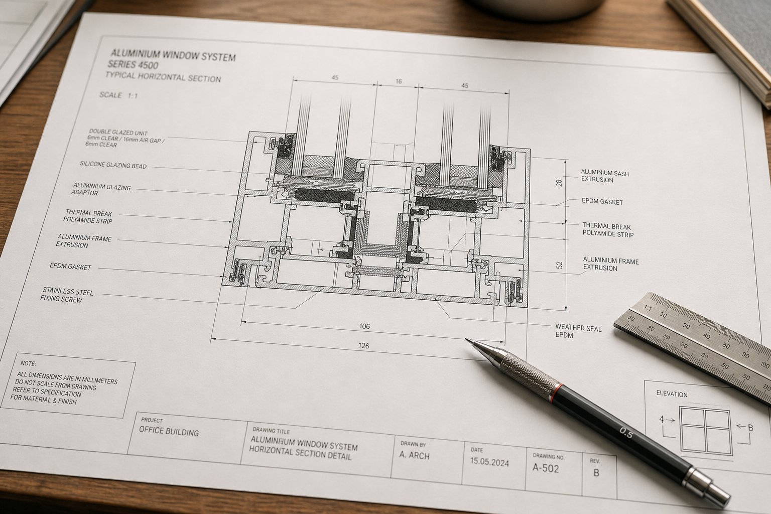
Drawing Conventions and Symbology in Window Sections
A perfectly resolved window junction means nothing if the person reading the drawing cannot tell aluminium from insulation, or sealant from a thermal break. That is where drawing conventions come in. Every material cut through in section carries a distinct graphic pattern, and understanding these aluminium window section drawing symbols is what separates a confident reading from a confused one.
Whether you are an architect specifying a system, a builder interpreting shop drawings on site, or a student learning how to read window detail drawings for the first time, the graphic language is the same. It follows conventions rooted in Australian Standards and widely adopted CAD practices, giving everyone on the project a shared visual vocabulary.
Material Hatching and Pattern Conventions
Hatching patterns act as a material key embedded directly into the aluminium drawing. Rather than labelling every single component, the drafter applies a standard hatching style that trained eyes recognise immediately. In window section details, you will encounter a relatively small palette of materials, but confusing any two of them can lead to misinterpretation of how the assembly performs.
| Material | Hatch Pattern | Where It Appears in Window Sections |
|---|---|---|
| Aluminium extrusion | Closely spaced diagonal cross-hatching (two directions at 45 degrees) | Frame profiles, glazing beads, pressure plates, mullions |
| Glass | Single thin diagonal line at each end of the pane, with the centre left clear | Glazing units shown in section through sash or fixed panel |
| Sealant / silicone | Solid black fill or dense stipple | Perimeter seals between frame and structure, weather seals at glazing rebates |
| Insulation (rigid or batt) | Irregular sinusoidal curves (wavy lines) | Cavity infill around frame, thermal break zones in older detail styles |
| Concrete / masonry | Triangular aggregate pattern with dots and irregular shapes | Lintel above head, sill substrate, blockwork at jambs |
| Timber | Irregular curved grain lines | Timber reveals, packing blocks, stud framing behind the frame |
| Thermal break (polyamide) | Distinct solid dark strip or unique fill contrasting with surrounding aluminium | Separation between inner and outer aluminium faces within the profile |
| EPDM rubber gasket | Solid black or dark grey fill in a small, shaped profile | Compression seals at sash-to-frame junctions, glazing gaskets |
One thing that catches people out: the thermal break strip sits inside the aluminium profile, splitting it into two separate pieces. In a well-drawn section, this element reads clearly as a non-metallic insert because its hatch or fill contrasts sharply with the aluminium cross-hatching on either side. If a reviewer cannot identify the thermal break location, the detail will likely be queried for NCC energy compliance.
Glass representation deserves a closer look as well. In section, each pane of a double-glazed unit appears as a thin rectangle. The convention is to mark diagonal lines at the top and bottom corners of the pane, leaving the middle clear, which instantly distinguishes glass from any solid material. The air gap or gas-filled cavity between panes shows as a blank space, sometimes annotated with the gas type and cavity width (e.g., 12 mm argon).
Reading Dimensions and Annotations in Window Sections
Beyond hatching, the window drawing conventions for dimensioning follow a clear hierarchy. Standard annotation practice places overall dimensions on the outermost line, with progressively finer detail dimensions stepping inward toward the object. In a window section, that typically means the overall reveal-to-reveal opening dimension sits outermost, the frame depth and sight-line dimensions sit on the next layer, and individual component sizes (gasket width, glazing rebate depth) appear closest to the profile.
Dimension lines use ticks or arrows to cross extension lines, and they never touch the object itself. This offset keeps the drawing clean, even when a section carries 15 or more individual measurements. Level markers, shown as a small arrow with a number indicating the height above finished floor level, anchor the detail vertically on the building.
Annotations and leader lines call out materials that hatching alone cannot fully explain. A leader pointing to a sealant fill might read “10 mm neutral-cure silicone to AS 1487”, giving both the material and the performance standard in a single callout. For builders interpreting the detail on site, these annotations bridge the gap between the graphic pattern and the specific product to be installed.
Consistency is what ties it all together. An office that uses solid black for sealant in the head detail but stipple for the same material in the sill detail creates unnecessary confusion. The best drawing sets include a hatch key or legend on the first sheet, referencing every pattern used throughout the package. That single addition can save hours of back-and-forth during construction.
Graphic conventions establish a shared language, but the real complexity emerges when different window operation types demand different profile geometries. Hardware pockets, drainage channels, and weatherseal locations all shift depending on whether the window is fixed, hinged, or sliding, and those changes reshape the section drawing entirely.
How Drawing Details Change Across Window Operation Types
A fixed window and a bifold window might share the same aluminium alloy and glass unit, but their section drawings look nothing alike. The moment a sash needs to move, whether hinging, sliding, or folding, the profile must accommodate hardware, weatherseals, drainage, and clearance gaps that a fixed frame simply does not require. That is why most aluminium profile suppliers organise their technical libraries by operation type rather than by size or finish.
Each operation type introduces distinct geometry into the section drawing. Recognising those differences helps architects specify correctly and helps builders identify what they are looking at when reviewing shop drawings on site.
Fixed and Awning Window Detail Differences
Fixed windows produce the simplest section profiles in any drawing set. There is no sash-to-frame junction, no hinge pocket, and no lock keep to accommodate. The glass sits directly in the outer frame via glazing beads and EPDM gaskets, and the profile depth stays compact. In section, you see a clean outline: outer frame, thermal break, glazing rebate, and bead. That is it.
An awning window detail drawing introduces a second aluminium element, the sash, nested inside the outer frame. Because the sash hinges outward from the top, the profile must include friction stay housings along the jambs and a clearance gap at the sill that allows the sash bottom rail to swing clear. Weatherstrips compress between the sash and frame when closed, and the drawing shows their exact position within purpose-milled grooves. Drainage slots appear at the bottom of the sash rail, directing any water that enters the rebate back outside. The profile depth increases noticeably compared to a fixed equivalent because of this doubled framing arrangement.
Sliding, Bifold, and Casement Profile Variations
A sliding window drawing detail looks fundamentally different from a hinged type. Instead of a single frame plane, the section reveals parallel tracks, typically two or three, each carrying a sash on nylon rollers. The interlock between meeting stiles uses brush pile or fin seals rather than compression gaskets, and the frame depth is driven by track count. Drainage channels run along the bottom rail of each track independently, with weep slots positioned behind the outer weatherseal line.
The casement window section detail shares DNA with the awning type but rotates the hinge axis to the vertical jamb. Hardware pockets for espagnolette locks run along the stile opposite the hinge side, requiring a deeper profile on that edge. Multi-point locking mechanisms add further recesses into the frame that appear as rectangular voids in the section drawing. Compression seals sit in two or three continuous lines around the sash perimeter, visible as small black-filled shapes in the detail.
A bifold window section detail carries the most complexity. Each folding leaf has its own sash profile with hinge knuckle provisions, plus a top-hung track that bears the full panel weight. The stacking depth when open, the clearance between adjacent leaves, and the reinforced corner joints all influence the profile geometry. In the drawing, you will notice wider mullion sections at the lead panel, heavier bottom pivots with integrated drainage, and additional weatherseal lines compared to any other type.
| Operation Type | Hardware Provisions in Section | Drainage Strategy | Weatherseal Location | Relative Profile Depth |
|---|---|---|---|---|
| Fixed | None (glazing beads only) | Frame base weep slots | Gasket at glazing rebate | Shallowest |
| Awning | Friction stay housing at jamb | Sash bottom rail weep slots | Compression seal at sash perimeter | Moderate |
| Casement | Espagnolette lock pocket, hinge rebate | Sash bottom rail and frame sill weeps | Multi-line compression seals | Moderate to deep |
| Sliding | Roller track channel, interlock fins | Independent channel per track | Brush pile or fin seals at interlocks | Deep (increases with track count) |
| Bifold | Top track carrier, pivot housing, hinge knuckle | Bottom pivot drainage, track channel weeps | Multi-line seals plus brush pile at folds | Deepest |
Matching the correct detail type to the specified window operation sounds obvious, but mixed-up drawings remain one of the most common reasons submissions bounce back. A detail showing a fixed profile where an awning was scheduled, or a two-track sliding section where a three-track unit was quoted, will trigger immediate queries from certifiers or fabricators. Checking that every section on your sheet corresponds to the window schedule eliminates a whole category of avoidable rejections.
Profile geometry tells only part of the story, though. Buried within each of these sections is the thermal break, a small component that fundamentally changes how the aluminium behaves in terms of energy transfer, and its presence or absence reshapes the drawing in ways that go well beyond hardware and seals.
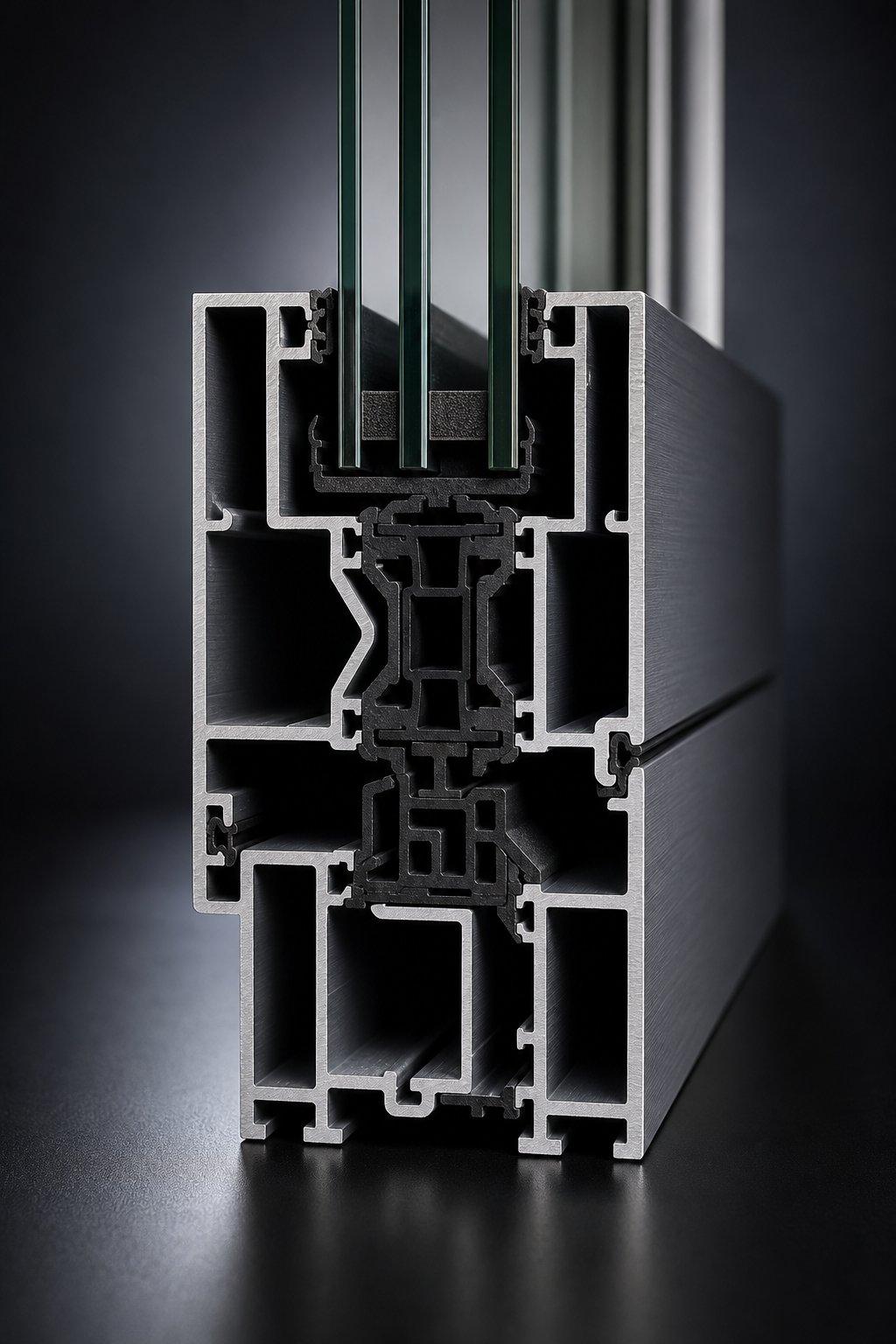
Thermal Break Technology in Aluminium Profile Drawings
Strip away the hardware and glazing from any modern aluminium window section, and one component dictates more about performance than anything else: the thermal break. In a thermal break window section drawing, this element appears as a distinct non-metallic insert physically splitting the aluminium extrusion into two separate shells. It is small in cross-section, often only 20 to 35 mm wide, yet it reshapes the entire profile geometry and determines whether the window meets NCC energy provisions or falls short.
How Thermal Breaks Appear in Section Drawings
In a thermally broken aluminium window detail, the break reads as a solid dark strip or uniquely filled band sandwiched between two aluminium sections. The interior shell faces the conditioned space. The exterior shell faces the weather. Between them sits a polyamide strip, typically PA66 reinforced with 25% glass fibre, bonded into precision-machined grooves on each aluminium piece. Because polyamide insulates roughly 500 times more effectively than aluminium, heat trying to conduct through the frame stalls at this point.
Older systems used a pour-and-debridge method, where liquid polyurethane was poured into a channel in a single extrusion, allowed to cure, then the aluminium bridge between the two faces was mechanically cut away. In section drawings, pour-and-debridge profiles look slightly different: the insulating core has an irregular shape rather than the clean rectangular strip of modern extruded polyamide. Both approaches achieve the same goal, splitting the thermal path, but extruded polyamide strips dominate current Australian supply due to their superior structural consistency and thermal performance.
When reviewing an aluminium window profile detail for thermal compliance, look for the following components visible in the section:
- Polyamide strip — the primary insulating barrier between interior and exterior aluminium faces, shown as a contrasting fill within the profile
- Pressure plate — an external aluminium capping piece that mechanically retains the glazing unit against the gaskets, fastened through to the frame
- EPDM gasket — rubber compression seals shown as small solid-black profiles at sash junctions and glazing rebates, maintaining airtightness
- Glazing bead — the internal snap-fit or screw-fixed aluminium trim that locks the glass unit into the rebate from the room side
- Drainage slot — small openings at the base of the glazing rebate and frame sill, drawn as breaks in the profile outline, allowing trapped water to escape
Impact of Thermal Technology on Profile Geometry
A non-thermally broken frame is a single extrusion, compact and shallow. Introducing a thermal break adds material depth. The two aluminium shells each need sufficient wall thickness for structural integrity, and the polyamide strip between them adds its own width. The result is a deeper overall profile, typically 55 to 75 mm for residential thermally broken systems compared with 35 to 45 mm for non-broken equivalents.
That increased depth has a direct visual consequence in the section drawing: more internal chambers become visible. Premium thermally broken profiles contain six to nine air chambers within their geometry, each acting as an additional insulating pocket. These chambers appear as enclosed voids in the cross-section, separated by thin aluminium webs. More chambers generally means better thermal and acoustic performance, but also a bulkier frame presence on the elevation.
For Australian projects assessed under NatHERS modelling or WERS ratings, the thermal break width is a critical variable. A wider break pushes the frame U-value lower, improving the whole-window energy rating. Reviewers checking compliance will look for the break clearly depicted and dimensioned in the section drawing. If the detail shows a single continuous aluminium profile with no visible separation, the window cannot claim thermally broken performance, regardless of what the specification schedule says.
Thermal breaks set the performance baseline, but performance does not end at the frame edge. How the entire assembly handles water, wind, and air pressure depends on components that extend beyond the profile itself, from weatherseals and drainage paths to the flashings that tie the window back into the building envelope.
Connecting Drawing Details to Window Performance Criteria
Every performance rating printed on a window schedule, water resistance, air infiltration, wind load, traces directly back to physical components you can point to in the section drawing. The detail is not a separate document from the performance specification; it is the specification made visible. When a certifier reviews an aluminium window drainage detail and queries a missing weep slot, they are not being pedantic. They are flagging a gap between the claimed rating and the documented assembly.
Weatherproofing Components Visible in Details
Water management in an aluminium window relies on a layered defence rather than a single seal. Research into pressure-equalised window installations demonstrates that open drainage paths combined with an uncompromised air barrier outperform face-sealed approaches over time, because any sealant eventually degrades and trapped water has no escape route. In a window weatherproofing detail drawing, this philosophy translates into specific elements:
- Weather seals — compression gaskets at the outer face that deflect bulk water and allow controlled air exchange behind them
- Drainage slots — openings at the base of the glazing rebate and frame sill that evacuate water reaching the cavity, shown as breaks in the profile outline
- Pressure equalisation chambers — enclosed air pockets within the frame profile that balance exterior wind pressure, reducing the driving force pushing water inward
- Sub-sill flashing — a membrane beneath the frame sill that collects bypass water and directs it outward over the wall face below
- Head flashing — a metal or membrane tray dressed over the lintel and lapping down behind the frame head, preventing moisture from the outer leaf migrating into the opening
The window flashing detail section deserves particular attention because it represents the boundary where the window system hands off to the building envelope. A sill flashing that terminates short of the wall face or lacks an upstand at its back edge will allow water to pool against the frame underside. At the head, a flashing tray without adequate side dams lets water flank around the ends and drip inside the reveal. These are common rejection triggers because they break the continuity of the weatherproofing line.
In Australian conditions, coastal exposure and cyclone-rated regions governed by AS 2047 demand higher water resistance classifications. The drawing must show that drainage capacity and seal compression match the pressure differential the window will face. A system rated to 300 Pa water resistance needs demonstrably more robust sealing and wider drainage channels than one rated to 150 Pa, and those differences must be legible in the section.
Linking Drawing Details to Performance Specifications
Specifiers use drawing details as a verification tool well before any aluminium gets fabricated. When a project requires, say, a wind load rating of N3 for a cyclone-prone site in northern Queensland, the reviewer examines the section for structural reinforcement: thicker aluminium walls, steel inserts within mullion chambers, or closer fixing centres back to the structure. If the detail shows a standard residential profile without reinforcement, the claimed rating has no visible support.
Air infiltration works the same way. AS 2047 tests air leakage at a set pressure differential, and the components controlling that outcome, continuous EPDM gaskets, multi-point compression seals, and an unbroken airtightness line from head through jambs to sill, must all appear in the drawings. A single discontinuity, such as a seal ending abruptly at a corner junction without a vulcanised corner piece, raises a valid compliance question.
The practical discipline here is straightforward: every performance claim on the window schedule should be traceable to a physical component visible in the corresponding section detail. If you cannot point to the element that delivers a specific rating, the drawing is incomplete, and the submission will come back with questions.
Performance criteria anchor a window’s value proposition, but they also vary with orientation. Overhead glazing and skylights face an entirely different set of forces, where gravity works against the seals rather than assisting drainage, demanding specialised details that vertical windows never encounter.

Appropriate Detail Levels Across Project Stages
Submitting fully detailed window sections during a concept design presentation wastes effort. Producing only single-line representations at construction documentation stage gets the drawings rejected. The level of detail embedded in aluminium windows drawing details needs to match the project phase, and misjudging that match is one of the quieter reasons submissions stall.
Construction projects move through distinct stages, each demanding progressively more information from the drawing set. The BIM Level of Development (LOD) framework formalises this progression, scaling from rough massing at LOD 100 through to as-built accuracy at LOD 500. Window details follow the same logic, even in traditional 2D workflows.
Detail Levels from Concept to Construction Documentation
Each project phase carries different expectations about what the window section should communicate and who is responsible for producing it:
- Concept design (LOD 100–200) — Windows appear as single-line or double-line representations in wall sections. No profile geometry, no material hatching, no component breakdown. The architect indicates opening locations, rough sizes, and general intent. A rectangle with a diagonal cross is often sufficient. The purpose is spatial planning and feasibility, not specification.
- Developed design (LOD 200–300) — Indicative profiles replace the schematic lines. The section shows approximate frame depth, glazing position, and general thermal break location without committing to a specific manufacturer or system. Material hatching begins to appear. The architect uses these to coordinate with structural engineers over lintel sizes and with energy consultants over thermal modelling inputs. Enough information exists to confirm the window will fit the wall build-up.
- Construction documentation (LOD 350–400) — Fully resolved sections with every component drawn: exact extrusion profiles, gasket positions, drainage slots, flashing interfaces, fixing details, and full dimensioning. Material callouts reference specific products and applicable Australian Standards. At this stage, details often flow from the window fabricator back to the architect as shop drawings, which are then reviewed and incorporated into the issued-for-construction set.
- As-built documentation (LOD 500) — The final record captures what was actually installed, including any site variations. These details support future maintenance, renovation, or compliance audits and reflect the completed assembly rather than design intent.
The critical handoff happens between stages three and four. During construction documentation, the architect produces performance-based details showing required outcomes. The fabricator then responds with system-specific shop drawings showing how their particular extrusion achieves those outcomes. This back-and-forth is where most coordination gaps open up. If the architect’s detail assumes a 65 mm frame depth but the fabricator’s system runs 72 mm, the wall build-up needs adjustment before anything gets manufactured.
CAD Blocks and BIM Families for Efficient Detailing
Redrawing window profiles from scratch for every project burns hours that most practices cannot afford. That is why window CAD block libraries and parametric BIM families exist. They provide pre-drawn, manufacturer-accurate section profiles that drop directly into project files.
In 2D workflows, AutoCAD window blocks typically ship as DWG files organised by system series and operation type. A drafter downloads the relevant head, sill, and jamb blocks, inserts them at the correct scale, and adapts the surrounding wall build-up to suit. The window detail CAD drawing download usually comes direct from the system supplier’s technical resources page, ensuring the profile geometry matches current production tooling rather than an outdated catalogue.
BIM workflows take this further. An aluminium window Revit family is not just a graphic; it is a parametric object carrying embedded data. Frame depth, thermal break width, glazing thickness, and U-value all live inside the family as editable parameters. When the energy modeller pulls performance data from the model, those values feed directly into NatHERS calculations without manual transcription. Changing the window size automatically updates the section detail on the sheet, keeping drawings and schedules synchronised.
The practical advantage is consistency. When every window on a project references the same family or block library, hatching patterns stay uniform, dimensions update automatically, and the risk of mismatched details between sheets drops significantly. Firms that maintain curated libraries of verified blocks spend less time on drawing production and more time resolving the interface conditions that actually require design thought.
Whether working in CAD or BIM, the underlying principle holds: use the right fidelity at the right time, and source your profile geometry from the system being specified rather than a generic approximation. Generic details might pass review at developed design stage, but construction documentation demands product-specific accuracy, and that accuracy increasingly lives inside digital objects rather than hand-drawn linework.
Standard vertical windows benefit enormously from these templated workflows. Skylights and overhead glazing, however, introduce forces and failure modes that no standard block library fully addresses, pushing the detailing process into territory where gravity becomes the enemy rather than the drainage ally.
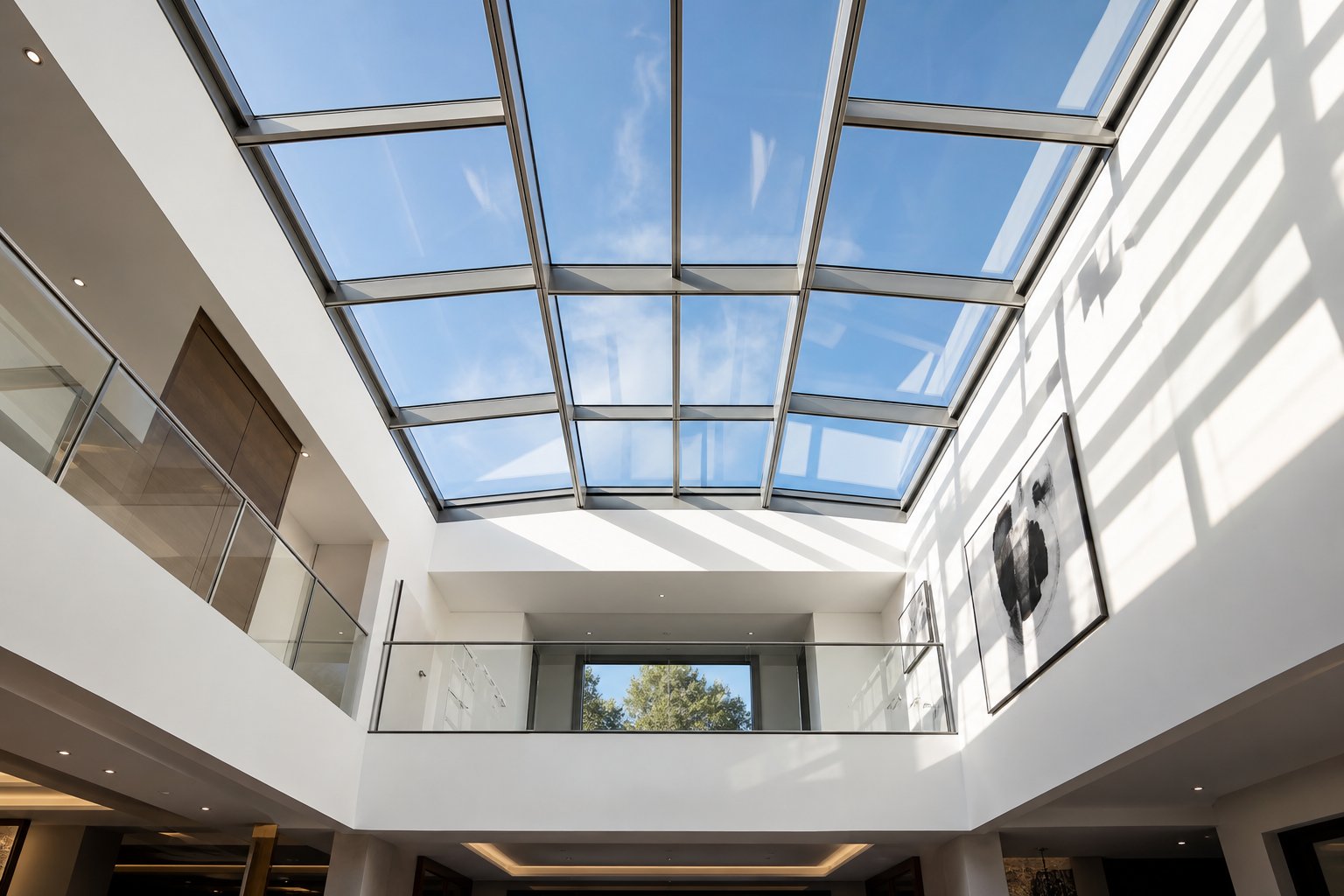
Skylight and Overhead Glazing Drawing Details
Rotate a window section drawing 90 degrees so the glass faces the sky, and almost every assumption built into the detail breaks down. Gravity no longer helps drain water off the sill. It now pushes down on every seal, trying to force moisture inward. That single shift in orientation makes skylight detail documentation a specialised discipline that borrows the visual language of vertical window sections but rewrites the engineering logic behind them.
Key Differences in Skylight Section Details
A vertical aluminium window relies on gravity to move water downward through drainage channels and out through weep slots. A skylight must fight that same force. Water landing on overhead glazing pools at low points rather than shedding naturally, and condensation forming on the inner glass face drips directly into the space below unless the framing captures and redirects it. Industry data on commercial skylight failures confirms that water management breakdowns, not glass defects, cause the vast majority of leak-related service calls.
The following considerations appear in skylight drawing details but are absent or minimal in standard vertical window sections:
- Enhanced drainage capacity — Internal gutter channels within the aluminium framing must be oversized compared to vertical equivalents, with multiple weep paths positioned to evacuate water before it reaches seal lines
- Condensation management — Dedicated condensation channels capture moisture forming on the inner glass face and route it to a sloping sill that drains externally, preventing dripping into occupied spaces
- Safety glazing mandates — AS 1288 requires laminated glass on the inner pane of any overhead glazing assembly so that broken fragments remain adhered to the interlayer rather than falling onto occupants below
- Gravity loading on seals — Gaskets must resist sustained dead-load compression from the glass weight pressing outward, demanding stiffer EPDM compounds and mechanical retention rather than friction-fit glazing beads
- Thermal movement allowance — Aluminium framing and glass expand at different rates under direct solar exposure, so the detail must show adequate clearance and flexible setting blocks that accommodate differential movement without opening seal joints
- Flashing upstands — The junction between skylight curb and roof membrane requires a minimum upstand height (typically 150 mm under NCC requirements) with the membrane dressed up and over the curb before the frame sits on top
- Fall-arrest provisions — For maintenance access, the drawing may need to show anchor points or walkway zones adjacent to the skylight, particularly on commercial projects governed by Safe Work Australia requirements
Framing and Flashing in Overhead Glazing Drawings
A skylight framing diagram differs from a vertical window schedule because it must communicate structural support connections that walls inherently provide but roofs do not. The drawing shows rafter or purlin members supporting the skylight curb, with the connection method detailed in section: bolted steel angles, welded brackets, or timber blocking between rafters. Span tables and member sizes appear as annotations because the glazing dead load plus any live load from maintenance access or hail impact must be resolved structurally before the weatherproofing layers are considered.
Flashing details around the curb perimeter carry more complexity than a standard head or sill condition. The upstand must integrate with the roof membrane as a unified waterproofing assembly, not as two separate systems that merely meet at the curb line. In section, you see the membrane lapping up the curb face, a metal counter-flashing capping the top edge, and insulation continuity maintained through the curb wall thickness to prevent thermal bridging at the perimeter. Without that insulation layer shown clearly in the drawing, condensation will form at the cold bridge and mimic a roof leak from the inside.
For practices working in BIM, skylight Revit families need to carry considerably more embedded data than standard window objects. Slope angle, structural loading parameters, glazing build-up specifying laminated inner panes, and drainage fall directions all live within the family definition. Getting these parameters right in the digital model means the extracted section details automatically reflect the unique requirements of overhead glazing rather than defaulting to vertical window logic.
Skylight details represent one end of the complexity spectrum for aluminium glazing documentation. Regardless of whether the project involves a single rooflight or a wall of bifolds, the terminology embedded in these drawings stays consistent. Understanding that shared vocabulary, and knowing where to source accurate, project-specific details rather than generic downloads, brings the entire documentation process together.
Technical Glossary and Sourcing Accurate Drawing Details
Every term that appears in aluminium windows drawing details carries a specific meaning tied to a physical component or interface condition. Misreading one label can cascade into an incorrect installation or a failed review. The glossary below collects the window drawing detail terms explained in plain language, giving architects, builders, and students a single reference point for the vocabulary embedded in these documents.
Glossary of Drawing Detail Terminology
These terms appear repeatedly across head, sill, jamb, mullion, and transom sections. Each one corresponds to something you can physically point to in the built assembly.
| Term | Definition | Where It Appears in Section Drawings |
|---|---|---|
| Thermal break | A low-conductance material (typically polyamide) inserted between the interior and exterior aluminium faces to interrupt heat transfer through the frame | Shown as a contrasting strip within the profile, separating inner and outer shells |
| Pressure plate | An external aluminium capping piece that mechanically clamps the glazing unit against its gaskets, secured with screws through to the frame | Outer face of the frame in curtain wall and commercial window sections |
| Glazing bead | A snap-fit or screw-fixed aluminium trim piece that retains the glass unit in its rebate from the interior side | Inner face of the glazing rebate, opposite the pressure plate or outer stop |
| Drainage slot | A small opening at the base of the glazing rebate or frame sill that allows trapped water to escape outward | Shown as breaks in the profile outline at the lowest point of the rebate cavity |
| Weather seal | A compressible gasket or fin positioned at the outer face of the frame-to-sash junction that deflects bulk water and wind-driven rain | Outer perimeter of the sash-to-frame interface, typically the first line of defence |
| EPDM gasket | Ethylene propylene diene monomer rubber seal used for weatherstripping and glazing retention due to its UV stability and compression recovery | Small solid-black profiles at sash junctions, glazing rebates, and frame perimeters |
| Polyamide strip | A glass-fibre-reinforced nylon (PA66 GF25) extrusion that forms the structural thermal break between aluminium faces | Inside the frame profile, bonded into machined grooves on each aluminium shell |
| Mullion | A vertical structural member joining two adjacent window panels within a single opening | Vertical section cuts showing a symmetrical profile with glazing retention on both faces |
| Transom | A horizontal structural member separating upper and lower panels, often at a floor line or operational change point | Horizontal section cuts showing load transfer and top-surface water shedding |
| Reveal | The visible return of the wall between the outer face and the window frame edge, formed by the depth of the frame set-back | Jamb details showing the plastered or rendered wall return from external face to frame |
| Sub-sill | A secondary sill component or flashing tray positioned beneath the main frame sill to capture bypass water and redirect it externally | Below the frame in sill section details, lapping over the wall face with a drip edge |
| Head flashing | A metal or membrane tray installed above the window frame, dressed over the lintel, preventing moisture penetration from above | Head details showing the flashing lapping down behind the frame top and into the cavity |
| Sill flashing | A waterproof membrane or metal tray beneath the window sill that collects water passing the primary seal and directs it outward | Sill details showing the membrane dressed up behind the frame and over the external sill edge |
This aluminium window terminology glossary is not exhaustive, but it covers the components most commonly queried during plan review. If a term appears in your section drawing and you cannot trace it to a physical element, ask the drafter for clarification before submitting. Assumptions that go unchecked at documentation stage tend to surface as costly site variations later.
Getting Project-Specific Details from Your Supplier
Generic CAD blocks downloaded from the internet solve a concept-stage problem. They give the architect an indicative profile to coordinate wall build-ups and confirm rough sizing. But they do not solve a construction documentation problem. At the point where drawings go to a certifier or a builder prices the job, the section details must reflect the actual system being quoted, with the correct profile depth, thermal break width, hardware provisions, and drainage configuration for that specific product.
That accuracy only comes from one place: the fabricator supplying the windows.
Reputable manufacturers and fabrication partners maintain technical teams that produce system-specific details matched to their current production tooling. These are not approximations or legacy drawings from a superseded catalogue. They are sections generated from the live extrusion dies, incorporating any recent profile updates, gasket changes, or hardware revisions. When a fabricator issues shop drawings for your project, those drawings carry the engineering backing of the system they are quoting, not a generic industry assumption.
The process of obtaining these details typically follows a practical sequence. The architect or builder provides the window schedule, floor plans, and elevations. The supplier reviews the scope, recommends appropriate systems for the performance requirements, and returns project-specific sections showing how their product integrates with the nominated wall build-up. For projects with complex interfaces, such as curtain wall transitions, corner assemblies, or structural glazing conditions, the supplier’s technical team produces bespoke details that no generic download could replicate.
For builders, developers, and architects working on Australian projects, partnering with a supplier that offers this level of drawing support from the outset eliminates much of the back-and-forth that delays submissions. MEICHEN’s services cover this workflow from initial schedules and system recommendations through to manufacturing coordination, giving project teams access to accurate section details tied directly to the product being fabricated rather than a theoretical profile.
The value of this approach becomes obvious when you consider how to get window shop drawings that actually pass review. A certified shop drawing from your fabrication partner carries weight that a generic internet download never will. It confirms the product exists, the profile is current, and the performance claims are testable against AS 2047. Certifiers recognise the difference immediately, and so do experienced builders who have been burned by mismatched details before.
Whether the project involves a single residential renovation or a multi-storey development, the principle holds: source your aluminium windows drawing details from the people manufacturing the product. Generic resources have their place during early design. But by the time your submission lands on a reviewer’s desk, every section detail should trace back to a real system, a real supplier, and a real commitment to deliver what the drawing promises.
Frequently Asked Questions About Aluminium Windows Drawing Details
1. What are the five standard aluminium window drawing detail types?
The five standard detail types are head (top of frame to lintel), sill (bottom of frame to substrate), jamb (side of frame to wall reveal), mullion (vertical joining member between panels), and transom (horizontal joining member). Each addresses a distinct interface condition where the window meets the building structure, and omitting any one from your submission typically triggers a request for further information from certifiers reviewing against AS 2047 and NCC requirements.
2. Why do aluminium window drawing submissions get rejected in Australia?
Common rejection reasons include missing sub-sill flashing membranes, unclear thermal break representation preventing NCC energy compliance verification, mismatched details where the section shows a different operation type than the window schedule specifies, and incomplete seal lines that raise air infiltration or water resistance concerns. Certifiers assess each junction individually against AS 2047 performance criteria, so every component delivering a claimed rating must be visible and correctly drawn in the corresponding section.
3. How do thermally broken aluminium window details differ from standard profiles?
Thermally broken profiles appear in section drawings as two separate aluminium shells connected by a contrasting polyamide strip, typically PA66 reinforced with 25% glass fibre. This insert interrupts heat conduction through the frame. The overall profile depth increases to 55-75 mm compared with 35-45 mm for non-broken equivalents, and additional internal air chambers become visible in the cross-section. For Australian projects assessed under NatHERS modelling, the thermal break must be clearly depicted and dimensioned to confirm energy compliance.
4. What level of detail should window drawings show at each project stage?
At concept design, windows appear as single-line or double-line representations indicating location and size only. Developed design introduces indicative profiles with approximate frame depth and thermal break position for coordination purposes. Construction documentation requires fully resolved sections with exact extrusion profiles, gasket positions, drainage slots, flashing interfaces, fixing details, full dimensioning, and material callouts referencing specific products and Australian Standards. Shop drawings from the fabricator provide the final product-specific accuracy needed for certification.
5. How do I get accurate aluminium window shop drawings for my project?
Accurate shop drawings come directly from the fabricator supplying the windows, not from generic online CAD downloads. The process involves providing your window schedule, floor plans, and elevations to the supplier, who then recommends appropriate systems and returns project-specific sections showing how their product integrates with your wall build-up. Suppliers like MEICHEN offer technical support covering schedules, system recommendations, and manufacturing coordination, ensuring the section details match current production tooling and carry the engineering backing needed to satisfy certifier review.
More Window & Door Guides