Understanding the Aluminium Window Reveal Detail
An aluminium window reveal detail is the construction drawing and built assembly that defines the visible surface running between the outer edge of the window frame and the finished face of the surrounding wall. It is not the frame itself, nor the wall finish — it is the transitional zone that connects the two. This zone controls how water drains, where sealant sits, how thermal energy transfers, and what shadow line the building presents to the street.
What Is a Window Reveal in Construction
In plain terms, the reveal is the return surface you see when a window sits within the thickness of a wall. Look at any window from the outside. The gap between the frame edge and the rendered or clad wall face — that recessed surface — is the reveal. It appears on the sides (jambs), the top (head), and sometimes the bottom (sill), though each of those elements carries its own specific detailing requirements.
The difference between a window reveal and a jamb catches many people out. The jamb is the vertical structural side of the opening — the framing timber or masonry that supports the window. The reveal is the finished visible surface applied over or adjacent to that structure. One is structural; the other is the architectural expression of the junction. On construction drawings, the reveal appears as a dimensioned depth measured from the wall’s finished face back to the frame edge, typically annotated with the frame setback distance.
Aluminium window reveal depth explained simply: it is the measurable distance the frame is set back from the outer wall plane. In residential builds, this might be 40–90 mm depending on wall construction. Commercial projects with thicker facade assemblies can push well past 100 mm. These dimensions drive everything that follows — waterproofing details, flashing lengths, and the proportional shadow that gives the facade its character.
Why the Reveal Detail Matters for Performance
The reveal is not decorative trim. It is the single most failure-prone junction in the window-to-wall connection. NSW Building Commission research found that 42% of recently completed strata buildings carry serious waterproofing defects, with window and door flashings identified as a common failure point — particularly where sealant deteriorates and flashings corrode, allowing water into the wall cavity.
The reveal detail is where design intent meets construction reality. Waterproofing, thermal management, and structural fixing all converge at this junction, and errors here account for the majority of window-related building defects.
A reveal detail drawn correctly on paper but built poorly on site leads to water staining around frames, mould growth on interior walls, and remediation costs that can reach ten times what correct installation would have required. The architectural shadow line everyone admires is really just evidence that the weatherproofing geometry is working as intended.
Getting this junction right depends heavily on understanding which reveal profile suits your wall type and climate exposure — a decision that starts with knowing what options exist.
Types of Aluminium Reveal Profiles Explained
Four distinct reveal configurations appear across Australian residential and commercial projects. Each produces a different relationship between the window frame and the wall surface — and each demands a different approach to waterproofing, fixing, and thermal management. Choosing the wrong profile for your wall type or climate exposure is one of the fastest paths to premature failure.
Flush Reveal and Recessed Reveal Profiles
The flush reveal vs recessed reveal difference comes down to one dimension: where the frame face sits relative to the finished wall plane.
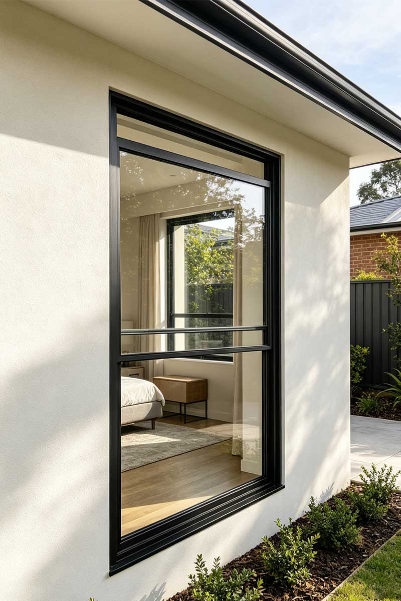
A flush reveal positions the outer face of the aluminium frame level with the external cladding or render surface. There is no visible depth — the frame and wall read as a single plane. This produces a clean, minimalist exterior with no shadow lines, and it integrates particularly well with rendered finishes, flat panel cladding, and contemporary facade systems. Flush reveals are common in modern Australian builds where architects want the glazing to disappear into the wall. However, the lack of depth means waterproofing relies almost entirely on the sealant joint between frame and finish, leaving very little tolerance for movement or sealant degradation.
A recessed reveal sets the frame back from the wall face, creating a visible reveal depth — typically 40 to 90 mm in residential construction, and up to 150 mm or more in commercial facade assemblies. This setback creates the characteristic shadow line that adds architectural texture and visual weight to the elevation. Recessed windows provide natural shading that can reduce solar gain through glazing in warmer months, making them a practical choice across much of Australia’s climate zones. The deeper the reveal, the more pronounced the shadow — but also the greater the surface area exposed to wind-driven rain, which demands careful flashing design at the head and jamb.
Most brick veneer and cavity masonry homes in Australia default to some version of a recessed reveal simply because the window sits within the wall thickness rather than at its outer face. The reveal depth is a byproduct of the construction system as much as it is a design choice.
Shadow Gap and Projecting Reveal Configurations
The shadow gap window reveal detail is a refined subset of the recessed approach, used heavily in contemporary minimalist architecture. Rather than a broad visible reveal surface, the shadow gap is a narrow recessed channel — typically 10 to 20 mm wide — between the window frame edge and the wall lining or cladding. The gap reads as a dark line rather than a surface, creating a precise separation that makes the window appear to float within the wall. Shadow gap reveals require tight construction tolerances and are most commonly specified in plasterboard-lined interior reveals or in external facades with sheet metal cladding where the gap can be maintained consistently.
The aluminium projecting reveal profile takes the opposite approach. Here, the frame or a dedicated reveal trim extends outward past the finished wall face. The projection might be a pressed aluminium surround that wraps the opening like a picture frame, standing 20 to 50 mm proud of the cladding. Projecting reveals create bold shadow lines on both sides of the trim, drawing the eye to the window as a deliberate architectural feature. They suit facades where the designer wants to punctuate the wall surface — breaking up large rendered planes or adding scale to commercial elevations.
Each of the four types of window reveal profiles carries distinct trade-offs:
- Flush reveal: 0 mm depth; seamless modern aesthetic; relies on sealant integrity; suits rendered and flat-panel cladding systems
- Recessed reveal: 40–150 mm depth; strong shadow lines; natural shading benefit; suits masonry, cavity wall, and thick framed assemblies
- Shadow gap reveal: 10–20 mm channel width; precise minimalist separation; demands tight tolerances; suits sheet cladding and internal plasterboard linings
- Projecting reveal: 20–50 mm projection past wall face; bold articulation; increased weather exposure on top edge; suits commercial facades and feature residential elevations
For inside reveal configurations — the interior-facing surfaces — the same four profiles apply in principle, though the priorities shift. Weather exposure drops away, and the focus moves to thermal comfort, condensation risk, and how the reveal interfaces with internal plaster or timber linings. A recessed internal reveal with a deep sill creates a usable ledge, while a flush internal detail keeps sightlines clean in compact rooms.
Profile geometry is only half the equation. The aluminium material itself — its thickness, alloy grade, and surface finish — determines whether the chosen reveal profile can perform over a 20-year service life or starts deteriorating within five.
Aluminium Material Specifications for Reveal Construction
A reveal profile is only as durable as the aluminium it is made from. Specifying the wrong thickness, alloy, or finish for your environment is a quiet failure — one that shows up years later as corrosion blooms, chalking surfaces, or trims that buckle under thermal cycling. Material selection is where longevity gets locked in or given away.
Alloy Grades and Sheet Thickness for Reveals
Aluminium reveal sheet thickness options typically range from 0.7 mm to 2.0 mm for press-brake formed flashings and trims. Lighter gauges (0.7–0.9 mm) suit internal reveal linings and protected locations where the material faces minimal mechanical stress. External reveals exposed to wind pressure, impact risk, and thermal movement need 1.2 mm as a minimum — with 1.6 mm or heavier common on commercial facades where spans between fixings are wider.
The best alloy grade for window reveals in architectural applications is typically from the 5000 series (such as 5005 or 5052) or the 3000 series (3003 or 3105). The 5000 series alloys offer superior corrosion resistance and excellent finish adhesion, making them the default choice for coastal and high-exposure environments across Queensland, northern NSW, and Western Australia’s coastline. The 3000 series provides good formability at a lower cost, which suits inland and urban projects where salt-air corrosion is less aggressive. Alloy 6063, an extrusion-grade aluminium, dominates where reveals are produced as extruded profiles rather than folded sheet.
Australian building codes require external metal flashings and trims to demonstrate a minimum 15-year durability for the intended exposure environment. In practice, correctly specified aluminium reveals routinely exceed this threshold — but only when the alloy, finish, and fixing system are coordinated.
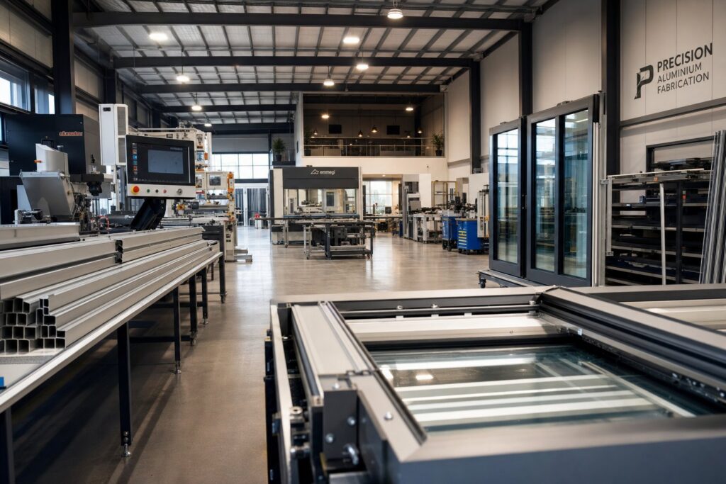
The choice between aluminium extrusion reveal vs sheet reveal depends on project complexity and volume. Sheet reveals are press-brake formed from flat aluminium coil, folded to the required profile on site or in a sheet metal shop. They offer maximum flexibility — any reveal depth, any angle — and suit one-off or low-volume residential work. Extruded reveals are pushed through a custom die to produce a fixed cross-sectional profile, often with integrated features like snap-fit legs, drainage channels, or thermal break grooves built directly into the section. Extrusions reduce on-site labour and eliminate folding tolerances, but they require upfront tooling investment that only makes economic sense at volume — typically commercial projects with repetitive opening sizes.
Comparing Reveal Material Options
The powder coated vs anodised aluminium reveal debate shapes appearance and maintenance for the life of the building. Anodising is an electrochemical process that thickens the natural oxide layer on the aluminium surface, producing a hard, UV-stable finish with a characteristic metallic sheen. It will not peel or flake because it is integral to the metal itself. Powder coating applies an electrostatically charged polymer layer that is oven-cured onto the surface, delivering a far broader colour palette — from standard Colorbond-matched tones to custom RAL colours — along with matte, satin, or gloss texture options.
For coastal projects, anodising provides inherent corrosion protection without relying on a separate coating layer to remain intact. For projects where colour matching to surrounding cladding or joinery is essential, powder coating wins on flexibility. Raw mill finish — untreated aluminium — is occasionally specified for concealed flashings behind cladding where appearance is irrelevant and cost is the priority, but it should never be left exposed externally in salt-air or industrial environments.
| Material Option | Durability | Thermal Performance | Cost Bracket (AUD) | Maintenance | Forming Flexibility |
|---|---|---|---|---|---|
| Aluminium sheet (press-brake formed) | 20–40+ years with correct finish | Low inherent insulation; relies on assembly design | $$ — moderate | Minimal; periodic cleaning | Excellent — any profile achievable |
| Aluminium extrusion (die-formed) | 20–40+ years; integrated features reduce joint failures | Can incorporate thermal break geometry in profile | $$$ — higher upfront (tooling), lower per-unit at volume | Minimal; snap-fit reduces sealant reliance | Fixed to die profile; changes require new tooling |
| Timber with aluminium capping | 15–25 years; timber substrate vulnerable if cap fails | Good — timber provides natural insulation | $$$ — labour intensive | Higher; cap joints must be inspected regularly | Limited by timber substrate dimensions |
| Composite (aluminium-faced foam core) | 15–20 years; delamination risk in high-heat exposure | Moderate — foam core adds insulation value | $$ — moderate | Low if joints remain sealed | Good for flat panels; limited on tight folds |
Aluminium sheet and extrusion options dominate Australian reveal construction for good reason — they combine corrosion resistance, forming versatility, and decades-long service life without the substrate vulnerabilities of timber or the delamination risks of composite panels. The deciding factors are project scale, budget, and whether integrated features like thermal breaks or drainage channels justify the tooling cost of extrusion.
Material selection locks in the reveal’s physical properties, but those properties only perform when the reveal is correctly integrated into the specific wall system it sits within — cavity masonry, timber frame, steel frame, or concrete — each of which demands a different installation approach.
Reveal Details by Wall Construction Type
A perfectly specified aluminium reveal trim bolted into the wrong position within a wall assembly will fail just as surely as a cheap one installed correctly. The wall construction type dictates everything — reveal depth, frame setback, waterproofing sequence, and the fixing substrate available to receive screws or rivets. Australian housing stock spans cavity masonry, brick veneer, timber frame with cladding, lightweight steel frame, and concrete construction. Each system positions the window differently within the wall thickness, and each demands a distinct reveal strategy.
Reveal Details for Masonry and Concrete Walls
The window reveal detail in a cavity brick wall is shaped by the cavity itself. In standard cavity masonry — two leaves of brickwork separated by a 40–50 mm air gap — the aluminium window frame typically sits on the inner leaf, positioned within or just behind the insulation zone. The outer brick leaf returns at the opening to form the structural reveal, and the visible reveal depth equals the distance from the outer face of that return brick back to the frame edge. In most cases, this produces a reveal depth of 90–110 mm on the exterior.
Waterproofing at this junction relies on cavity flashings that direct moisture out from the cavity to the external face. At the head of the window, a flashing must extend at least 150 mm past each side of the opening and integrate with the lintel. The NSW Building Commission notes a common defect where flashing and lintel lengths do not match, creating a gap that allows water to track down inside the cavity rather than being discharged outward. At the sill, the cavity flashing falls to the outside with weepholes at maximum 1200 mm centres draining any collected moisture.
Damp-proof courses interact directly with reveal flashings at lower openings. Where the window sill sits close to a DPC line, the two membranes must lap correctly — the DPC preventing rising damp and the flashing directing cavity moisture outward. Under the Deemed-to-Satisfy pathway, windows in masonry construction must comply with AS 2047, with flashings meeting AS 4773.2 requirements. Fixing the aluminium frame into masonry typically uses galvanised mild steel straps or brackets anchored into the blockwork inner leaf at regular centres, allowing the frame to bridge across the insulation zone without creating a direct thermal bridge to the outer skin.
Brick veneer — Australia’s most common residential wall system — simplifies the reveal geometry slightly. The single outer brick leaf sits in front of a framed inner wall with a 40 mm minimum cavity between them. The window frame fixes directly to the timber or steel studs of the inner frame, and the reveal depth equals the brick thickness (110 mm) plus the cavity width minus whatever frame projection exists. Aluminium reveal flashings wrap from the frame outward, lapping over the building wrap on the inner frame and discharging above the brick course below the sill.
The window reveal detail in concrete wall construction follows a different logic. In tilt-up and in-situ concrete panels, the opening is cast or cut into the slab, leaving a raw concrete surface as the reveal. These reveals are dimensionally precise — formed by the shuttering — but thermally unforgiving, since concrete conducts heat readily. Two approaches are common: either an aluminium reveal lining is fixed directly to the concrete surface using mechanical anchors and a bed of sealant, or the concrete is furred out with insulation battens and the reveal trim is then fixed over the insulated substrate. The first approach is faster; the second performs far better thermally. In commercial buildings, extruded aluminium reveal profiles with integrated drainage channels are often specified to slot over the concrete edge, held by concealed clip fixings that allow thermal movement without visible fasteners.
Reveal Details for Framed and Clad Walls
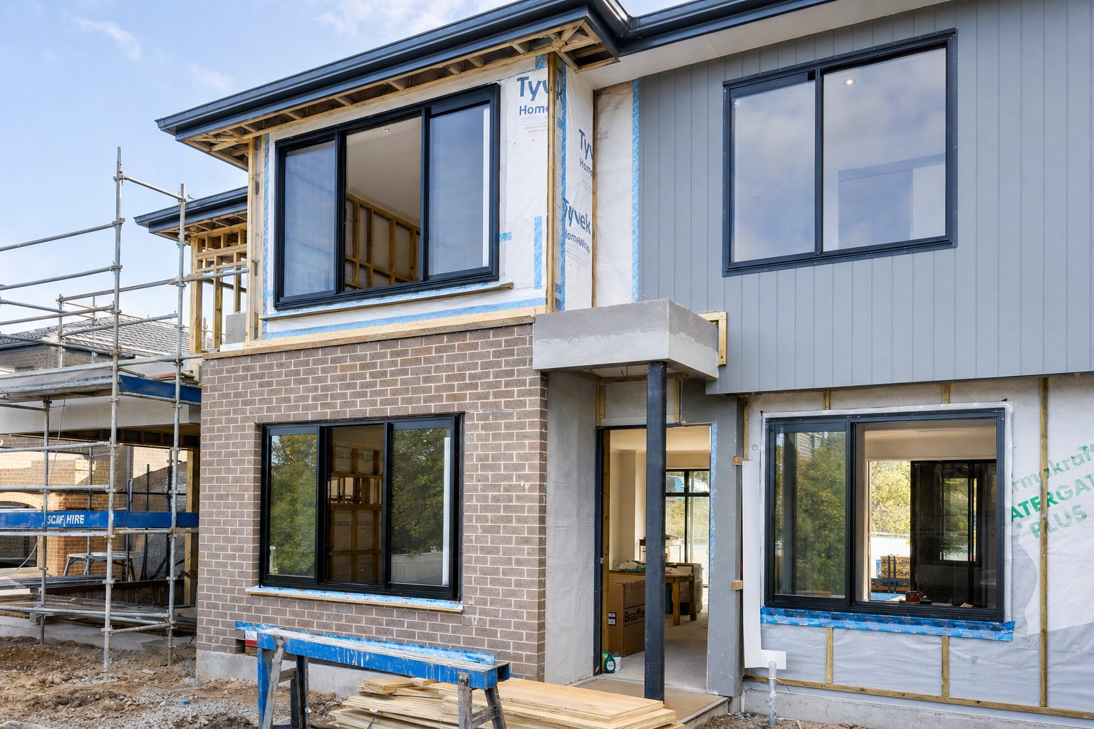
Timber-framed and lightweight steel-framed walls introduce a variable that masonry does not: the cladding system sits outboard of the structural frame, and the window can be positioned anywhere within that layered assembly. The aluminium reveal in timber frame construction depends on whether the window sits at the frame line (flush with the studs), pushed forward into the cladding zone, or centred within the insulation zone — which is the most common modern positioning for thermal performance.
When the window sits at the frame line, the external reveal depth equals the thickness of the insulation, air gap, and cladding combined. For a typical assembly — 90 mm stud with external insulation, 20 mm cavity batten, and 9 mm fibre cement sheet — this produces roughly 40–60 mm of external reveal depending on insulation thickness. The building wrap (sarking) is the primary waterproofing layer, and it must be dressed into the reveal opening before the window is installed. The wrap folds over the rough sill, up the jambs, and laps over the head — always shingled so that water hitting any surface is directed downward and outward, never behind the next layer.
The aluminium reveal trim or flashing is then sequenced with the cladding installation. The bottom flashing goes in first, sitting under the sill wrap and kicking water clear of the cladding below. Jamb flashings follow, lapping over the bottom flashing edges. Head flashing goes last, lapping over the jamb flashings — the same shingle principle that governs every layer of the envelope. Mechanical fixing into the timber frame is straightforward: stainless steel screws at 300–450 mm centres, with elongated holes in the aluminium to permit thermal expansion along the trim length.
Lightweight steel frame construction follows the same sequencing logic as timber frame, but the fixing substrate changes. Self-drilling screws into steel studs replace wood screws, and the thinner gauge of steel framing means fixings must hit the stud flange precisely — missing by even a few millimetres means the screw spins in air. Steel frame also amplifies thermal bridging concerns at the reveal, since the studs conduct heat far more readily than timber. Insulated reveal linings or thermal break pads between the aluminium trim and the steel substrate become important in climate zones where condensation risk is elevated.
Reveal flashing for rendered cladding adds another layer of complexity. When the external finish is acrylic render over polystyrene (EPS) or fibre cement sheet, the render terminates at the window frame — and this junction is one of the most crack-prone details in residential construction. Differential thermal movement between the aluminium frame and the rendered surface means a hard sealant joint will eventually crack. The correct detail uses a PVC or aluminium stop bead at the render edge, creating a defined termination line with a flexible sealant channel between the bead and the frame. The aluminium reveal trim may sit behind the render system entirely — acting as a concealed flashing — or it may be the visible finished surface, with render butting to its outer edge.
Regardless of wall type, one principle holds: the window frame position within the wall determines the reveal depth, and the reveal depth determines how much waterproofing, insulation, and flashing work must happen within that zone. Get the frame position wrong early, and no amount of clever trim detailing will rescue the thermal and moisture performance later.
Thermal Performance at the Aluminium Reveal Junction
Frame position determines reveal depth, and reveal depth determines how much space exists for one of the most overlooked performance factors in the entire window assembly: thermal management. Aluminium conducts heat at roughly 160 W/mK — around 400 times more readily than a polyamide thermal break and over 1,000 times faster than mineral wool insulation. When an aluminium reveal lining creates an uninterrupted metallic path between the cold exterior and the warm interior, it acts as a thermal highway, bleeding heat out of the building regardless of how well-insulated the surrounding wall might be.
This is the mechanism behind thermal bridging at aluminium window reveals. The reveal trim or lining, if it spans from the outer wall face through to the interior without interruption, conducts heat along its length far more efficiently than the insulated wall beside it. The result is localised cold spots on interior surfaces, elevated heating loads, and a measurable impact on the overall U-value of the window assembly — an impact that standard centre-of-glass calculations do not capture.
Thermal Bridging and Condensation at Reveal Surfaces
Condensation on window reveal surfaces is the visible symptom of thermal bridging at work. When internal surface temperatures at the reveal drop below the dew point of the room air — typically around 12–14°C in a home heated to 20°C with normal humidity — moisture condenses. This usually appears first in the corners where the reveal meets the window head, because rising warm air deposits moisture on the coldest available surface.
In southern Australian climates — Melbourne, Canberra, Hobart, and highland areas of NSW — winter overnight temperatures regularly drop below 5°C. An uninsulated aluminium reveal in these conditions can see its internal surface temperature fall to 8–10°C, well below condensation threshold. Over weeks and months, persistent condensation feeds mould growth, stains plasterboard linings, and creates long-term fabric damage that extends well beyond cosmetic concern.
The relationship between thermally broken and non-thermally broken window frames compounds the issue. A thermally broken frame uses a polyamide or polyurethane barrier within the frame profile to interrupt conductive heat flow — achieving whole-window U-values as low as 0.8 W/m²K in high-performance systems. But if that carefully engineered frame sits within a reveal assembly that conducts heat freely around the frame’s thermal break, the break is being bypassed. The cold path simply routes through the reveal lining instead of through the frame itself. Specifying a thermally broken window while ignoring the reveal thermal performance is like insulating a wall but leaving a strip of bare metal running through it.
Thermal Break Placement and Insulation Strategies
Reveal depth directly governs how much space is available for thermal management. A shallow 40 mm reveal leaves almost no room for insulation between the aluminium lining and the structural substrate. A deeper 90–120 mm reveal — common in brick veneer and cavity masonry — provides enough cavity to incorporate meaningful insulation and still maintain clearance for fixing and air movement.
Insulation within the reveal cavity is positioned between the structural opening (timber stud, masonry, or concrete) and the aluminium reveal lining. Rigid PIR (polyisocyanurate) board works well in this location — it provides high thermal resistance per millimetre of thickness, resists moisture absorption, and can be adhesive-fixed to the substrate before the reveal trim is installed over it. Even 20 mm of PIR (R-value approximately 0.9) makes a substantial difference to internal surface temperatures.
How to prevent thermal bridge at window junction comes down to interrupting the conductive path at one or more points. The following strategies can be applied individually or combined depending on climate zone and performance target:
- Thermal break strips: A polyamide or EPDM isolator placed between the aluminium reveal trim and any steel or aluminium structural fixing prevents direct metal-to-metal contact and breaks the conductive chain at the attachment point.
- Insulated reveal linings: Rigid insulation board (PIR or XPS) installed behind the aluminium reveal trim raises internal surface temperatures above dew point. For aluminium windows in NatHERS climate zones 6 and 7, this is increasingly a compliance necessity rather than an optional upgrade.
- Frame position optimisation: Positioning the window frame within the insulation zone of the wall — rather than at the inner or outer face — minimises the length of exposed reveal that sits outside the thermal envelope. This reduces the conductive path length and the area of cold surface on the interior.
- Vapour management at the reveal surface: In high-humidity environments (bathrooms, kitchens, laundries), a vapour control layer on the warm side of the reveal insulation prevents moisture-laden air from reaching the cold aluminium surface behind. Without this layer, condensation can form within the assembly rather than on the visible surface — hidden interstitial condensation that causes timber rot and corrosion.
Each strategy adds cost and complexity, but the payoff is measurable. Correctly detailed insulated reveal linings for aluminium windows can lift internal reveal surface temperatures by 4–6°C in winter conditions — often enough to eliminate visible condensation entirely and reduce localised heat loss by 30–50% compared to an uninsulated aluminium reveal.
Thermal performance and waterproofing are not independent systems — they share the same physical space within the reveal cavity and interact at every layer. When one fails, the other often follows. Water ingress wets insulation, destroying its thermal resistance. Condensation from thermal bridging saturates sealant substrates, accelerating adhesion failure. The next critical question is not whether these failures occur, but which specific failure modes strike first and how correct detailing prevents each one.
Common Reveal Failures and How to Prevent Them
Failure at the reveal junction rarely announces itself dramatically. A faint brown watermark at the corner of a window head. A hairline crack running along the render-to-frame interface. A powdery white deposit appearing on a fixing screw. These quiet signs represent the gap between what was drawn in a warm office and what was built on a windy scaffold — and each one traces back to a specific detailing or construction error that could have been avoided.
The aluminium window reveal detail is where multiple material systems meet under stress. Aluminium, sealant, render, timber, membrane, and fasteners all converge in a zone barely 100 mm wide, each expanding and contracting at different rates, each responding differently to moisture. When one element underperforms, the failure cascades through the others. Understanding the mechanism behind each common defect is the first step toward building reveals that hold together for decades rather than years.
Water Ingress and Sealant Failure at Reveal Junctions
Water leaking through window reveal details is the single most reported defect in Australian residential construction related to window assemblies. The paths water takes are predictable, and they exploit the same weaknesses every time.
The primary ingress route is through failed back-seals — the sealant joint between the rear of the aluminium frame and the structural opening or building wrap substrate. This joint sits hidden from view once the reveal trim is installed, making inspection impossible without destructive access. When it fails — through poor adhesion, UV degradation at exposed edges, or joint movement exceeding the sealant’s elasticity — water tracks behind the frame into the wall cavity. It may travel considerable distances before appearing internally, making the source difficult to trace.
A second common path runs around improperly dressed building wrap. The membrane should fold into the reveal opening in a specific shingle sequence: sill first, then jambs lapping over the sill membrane, then head lapping over the jambs. When installers reverse this sequence, or cut the membrane short rather than folding it fully around the reveal edge, wind-driven rain finds the unsealed lap and runs straight into the framing. This is a construction error, not a material defect — the building wrap works perfectly when dressed correctly, and fails completely when it is not.
The third path — and the one most commonly missed on drawings — is capillary action in tight tolerance gaps. Where the aluminium reveal trim sits within 3 mm of an adjacent surface without sealant, water is drawn into the gap by surface tension. It moves upward, sideways, and against gravity, defying what most people assume about how water behaves. Capillary bridges form at frame-to-sill junctions, behind snap-on cover plates, and in the narrow space between reveal trim and building wrap where fixings compress the assembly. The prevention is straightforward: either seal the gap entirely or open it beyond 6 mm to break capillary action. Anything in between invites trouble.
Correct sealant specification and joint design prevent the majority of water ingress failures at the reveal. The joint must accommodate thermal movement — aluminium expands approximately 2.4 mm per metre over a 100°C temperature range, which translates to roughly 0.5–0.7 mm of movement on a typical 600 mm reveal trim across seasonal temperature swings. A sealant joint designed at 10 mm width with a neutral-cure silicone (capable of ±25% movement) handles this comfortably. Joints specified too narrow, or filled with a sealant grade that cannot tolerate the movement range, will crack within three to five years. Backing rod diameter must be approximately 25% larger than the joint width to achieve the correct hourglass profile, which maximises elasticity and prevents three-sided adhesion — a common error where sealant bonds to the backing rod and tears under stress.
Preventing Cracking and Corrosion in Reveal Assemblies
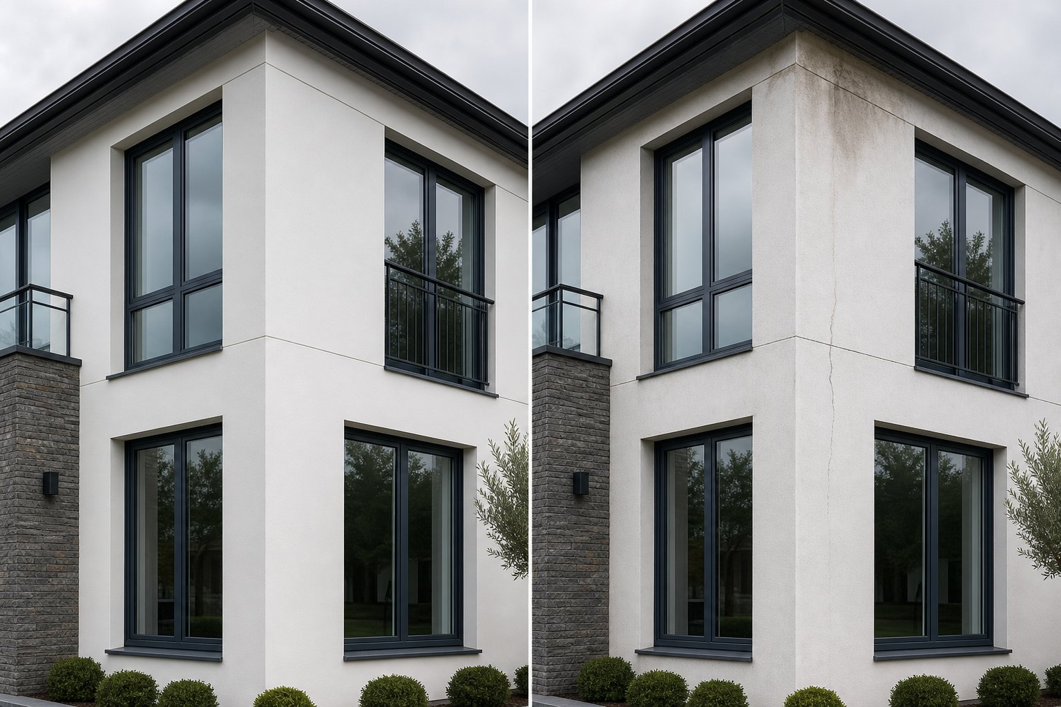
Render cracking around window reveals is so common that many builders treat it as inevitable. It is not. The mechanism is differential thermal movement: an aluminium frame heated by direct sun expands and contracts at a different rate to the acrylic or cement render abutting it. Temperature fluctuations cause building materials to expand in heat and contract in cold, and when the render mix is too rigid or the junction lacks a movement accommodation detail, cracks develop at the frame-to-render interface — typically within the first two summers after construction.
The render cracking around window reveal fix is a control joint or flexible sealant channel at the frame-to-render termination. A PVC or aluminium stop bead is installed at the render edge, creating a defined termination 5–8 mm from the window frame. This gap is then filled with a paintable polyurethane or silicone sealant that flexes with the differential movement. The bead prevents the render edge from feathering out to nothing (which always cracks), and the sealant absorbs the movement without fracturing. For best results, installing reinforcement mesh at stress points around windows distributes tension in the render coat and greatly reduces crack risk even before the stop bead detail takes over.
Galvanic corrosion at aluminium window reveals is less visible but potentially more damaging. It occurs when aluminium contacts a dissimilar metal — typically steel fixings, copper flashings, or lead work — in the presence of moisture. The electrochemical reaction causes the less noble metal to corrode far more rapidly than it would in isolation. In practice, this means mild steel screws fixing aluminium reveal trims will corrode aggressively wherever rainwater wets the junction, producing rust staining and eventually loosening the trim. Aluminium in contact with copper — common where copper roof flashings lap over aluminium window head trims — generates a galvanic cell that pits the aluminium surface and can perforate thin-gauge sheet within a few years in coastal environments.
Prevention requires material isolation. Stainless steel fasteners (grade 316 in coastal zones, 304 inland) are compatible with aluminium and do not generate significant galvanic potential. Where dissimilar metals must meet, non-conductive barriers such as plastic washers, neoprene gaskets, or specialised coatings at contact points interrupt the electrochemical circuit. Painting or powder-coating both surfaces at the contact zone also works, provided the coating is not breached by screw penetration or abrasion over time.
Taking all failure modes together, the most common reveal defects rank as follows in Australian residential and commercial construction, from most to least frequent:
- Sealant failure at frame-to-wall junction — Prevent with correct joint width (minimum 10 mm), neutral-cure silicone or polyurethane, proper backing rod installation, and two-sided adhesion geometry.
- Water ingress from incorrectly sequenced building wrap — Prevent by enforcing strict shingle order (sill, jambs, head) and verifying full membrane turn-in before frame installation.
- Render cracking at frame-to-reveal interface — Prevent with stop bead termination, flexible sealant channel, and reinforcement mesh in render coat at all window perimeters.
- Capillary bridging in narrow tolerance gaps — Prevent by either sealing gaps fully or maintaining a minimum 6 mm open dimension to break capillary path.
- Condensation and mould from thermal bridging — Prevent with insulated reveal linings and thermal break isolation between aluminium trim and structural substrate.
- Galvanic corrosion from dissimilar metal contact — Prevent with compatible fasteners (stainless steel), non-conductive isolators at all metal-to-metal contacts, and coating protection at fixing points.
- Trim buckling from restrained thermal movement — Prevent with elongated fixing holes allowing 1.5 mm movement per 600 mm of trim length, and expansion joints on runs exceeding 3 metres.
Every one of these defects shares a common thread: they arise not from exotic conditions or freak events, but from standard construction scenarios where a detail was drawn one way and built another — or never drawn at all. The gap between design intent and construction reality is widest at the reveal junction because it involves the most trade interfaces and the tightest tolerances. A bricklayer builds the opening, a carpenter installs the wrap, a glazier fits the frame, a renderer or cladder finishes the surface, and a plumber might even run a flashing through the assembly. Each trade arrives at a different time, works to a different tolerance, and answers to a different supervisor. Without a clear installation sequence and explicit quality checkpoints between trades, defects become almost guaranteed.
Knowing what fails — and why — creates the foundation for a construction methodology that builds these details correctly the first time. The question shifts from diagnosis to execution: in what order, with what fixings, and to what tolerances should an aluminium reveal assembly be installed to avoid every failure mode on this list?
Installation Methodology and Critical Tolerances
Execution is where reveal details live or die. A flawless drawing pinned to the site shed wall means nothing if the opening is out of plumb, the membrane is dressed backwards, or the trim installer arrives before the glazier has set the frame. The window reveal installation sequence steps must follow a rigid order — and each trade must verify the previous trade’s work before starting their own. Skip a check, and the defect gets buried under the next layer.
Step-by-Step Reveal Installation Sequence
How to install aluminium window reveal trim correctly depends on getting eight steps done in exact sequence. Each step includes a hold point — a quality verification that must pass before the next trade proceeds. Reversing steps two and three, or omitting step five, generates roughly 80% of the reveal defects listed in the previous section.
- Structural opening preparation: Confirm the rough opening is plumb, level, and square. Check dimensions at three points — top, middle, and bottom for width; left, centre, and right for height — and record the smallest measurement. Tolerance: opening must be within ±3 mm of nominal across any measured plane. Pack or trim framing as required. Hold point: sign off on opening dimensions before any membrane work begins.
- Waterproofing membrane installation: Dress the building wrap (sarking) into the reveal opening following strict shingle sequence — sill membrane first, folded down over the rough sill with a minimum 50 mm turn-up on the face. Jamb membranes next, lapping over the sill membrane by at least 100 mm. Head membrane last, lapping over the jamb membranes. All laps face downward so water sheds outward. Tape all laps with compatible flashing tape rated to the membrane system. Hold point: visual inspection confirming shingle direction and complete coverage before frame arrives on site.
- Sub-sill or sill flashing installation: Install a pre-formed metal or flexible sub-sill pan beneath the window frame position. This is the last line of defence if the frame seal ever fails — it collects any water that penetrates the primary seal and drains it to the exterior via end dams and a front lip that laps over the cladding below. End dams must turn up minimum 25 mm at each jamb. Hold point: water test the sub-sill before frame installation. Pour 500 mL of water into the pan and confirm it drains externally within 30 seconds with no leakage at corners or end dams.
- Window frame installation and fixing: Set the aluminium frame into the prepared opening on packers. Verify plumb, level, and square independently of the rough opening — the frame must be true regardless of any framing irregularity. Maintain a minimum clearance gap of 5–8 mm between frame and structure on all sides to allow for shimming, sealant, and thermal movement. Fix the frame to the structural substrate using brackets or direct-fix screws at maximum 450 mm centres (300 mm for commercial profiles or high wind zones). Hold point: check frame diagonals — difference must be less than 2 mm — and verify clearance gaps before reveal work proceeds.
- Back-seal application: Apply a continuous bead of neutral-cure silicone or polyurethane sealant between the rear of the frame and the building wrap or structural substrate. This seal is the primary water barrier at the frame perimeter and will be concealed by the reveal trim — it cannot be inspected or maintained once covered. Joint width should be 8–12 mm with sealant depth no greater than half the joint width. Hold point: photograph the completed back-seal before any trim covers it. This photographic record is critical for defect diagnosis if leaks appear later.
- Insulation and thermal break installation: Where specified (recommended in NatHERS climate zones 6, 7, and 8, or wherever condensation risk is elevated), install rigid PIR insulation board to the reveal substrate between the frame edge and the outer wall face. Minimum thickness 20 mm for residential, 30 mm for commercial. If aluminium reveal trim will fix to a steel substrate, install polyamide or neoprene thermal break pads at each fixing point to isolate metal-to-metal contact. Hold point: confirm insulation is continuous with no gaps at corners, and thermal break pads are positioned at all fixing locations.
- Aluminium reveal trim or lining installation: Fix the reveal trim to the structural substrate using the specified fixing method (see below). Begin with the sill trim, then jambs, then head — the same bottom-up sequencing logic that governs all weatherproofing layers. Each piece laps over the one below so water can never run behind a joint. Leave an aluminium reveal tolerance gap for thermal movement at all butt joints and end returns — typically 1.5 mm per 600 mm of trim length for external trims experiencing full sun exposure. Hold point: check all trim pieces for correct lap direction, verify expansion gaps at joints, and confirm fixings are in elongated holes (not round holes) to permit movement.
- Final sealant application and finishing: Apply the visible sealant joint between the outer edge of the reveal trim and the adjacent wall finish (render, cladding, or masonry). Joint width minimum 10 mm with correct backing rod installed to achieve two-sided adhesion. Tool the sealant to a slightly concave profile for maximum elasticity. Where cladding butts to the reveal, install a stop bead or Z-flashing to create a defined termination. Hold point: inspect all visible sealant joints for continuity, correct profile, and absence of voids or pinholes before scaffold is struck.
Each hold point represents a trade handover. The carpenter or framer owns steps one and two. The waterproofer or dedicated membrane installer handles step three. The glazier executes steps four and five. The insulator or general builder covers step six. A specialist flasher, sheet metal worker, or the window installer handles step seven. And the cladder or renderer closes out step eight. That is five or six different tradespeople touching one detail barely 100 mm wide — which explains why coordination failures are the norm rather than the exception.
Fixing Methods and Trade Coordination
The fixing methods for aluminium reveal flashing depend on the substrate receiving the fastener and the movement the trim must accommodate.
Screws are the most common fixing in residential construction. Stainless steel countersunk screws (grade 304 inland, 316 coastal) at 300–450 mm centres provide reliable pull-out resistance in both timber and steel substrates. The critical detail is the hole in the aluminium trim itself: it must be elongated (slotted) in the direction of anticipated thermal expansion — typically along the trim length — to allow the aluminium to slide over the screw shank as it expands and contracts. A round hole with a tight screw locks the trim in place and guarantees buckling or fastener fatigue within a few seasonal cycles.
Rivets suit thin aluminium sheet-to-sheet connections — fixing a folded reveal trim back to a concealed support angle, for example. Stainless steel or monel rivets prevent galvanic corrosion. Riveted joints are permanent and cannot accommodate movement, so they should only be used at the fixed point of the trim (typically one end or the centre), never at both ends.
Structural adhesive (high-strength polyurethane or epoxy) is used where no visible fasteners are acceptable — typically on projecting reveal surrounds or shadow-gap details where screw heads would break the design intent. Adhesive bonds spread load evenly and eliminate point-stress concentrations, but they are unforgiving of substrate contamination and require controlled curing conditions. They also make future trim removal or replacement significantly more difficult.
Clip systems are the premium solution for commercial and high-end residential projects. Concealed clips fix mechanically to the substrate, and the aluminium reveal profile snaps or slides onto the clip. The clip provides the structural connection while allowing the trim to expand freely along its length — no elongated holes required, no visible fasteners, and easy removal for maintenance. Extruded aluminium reveals are frequently designed with integrated clip receivers in the rear profile, making the system self-locating during installation.
The three-to-one rule provides useful guidance for sizing movement joints: design joints to accommodate at least three times the anticipated thermal movement plus fabrication and erection tolerances. For a 3-metre aluminium reveal trim in full sun (potential temperature differential around 50°C in Australian conditions), anticipated linear expansion is approximately 3.5 mm. Applying the three-to-one rule means the joint or movement allowance should accommodate at least 10.5 mm — accounting for the movement itself plus the variability in where the trim sits within its range at the moment of installation.
Window frame profile depth directly affects how the reveal trim is sized and how it fixes to the surrounding structure. A standard residential aluminium frame carries a profile depth of around 44–52 mm, while commercial thermally broken frames can run 70–100 mm deep. The deeper the frame profile, the less reveal depth remains for the trim to cover — because the frame itself occupies more of the wall thickness. In a brick veneer wall with a 150 mm total reveal cavity, a 50 mm residential frame leaves 100 mm for the reveal trim to span. A 90 mm commercial frame in the same wall leaves only 60 mm. This difference changes the trim proportions, the fixing geometry, and whether insulation can fit behind the lining.
Site tolerances bring the final complication. Drawn dimensions assume a perfect world — plumb walls, square openings, consistent cavity widths. Real openings on real sites deviate. The three-point measurement approach (measuring width and height at three positions and recording the smallest) accounts for this variability. Reveals specified at exactly the theoretical dimension will not fit on site without forcing — and forcing aluminium trims into undersized spaces puts them under stress that accelerates fatigue and buckling.
The practical response is to detail for real-world conditions: specify reveal trims 3–5 mm smaller than the theoretical opening dimension, and absorb the difference in the perimeter sealant joint. A 12 mm sealant joint works harder than a 10 mm joint, but it accommodates the ±2 mm variation that every site produces — and a functioning sealant joint is always preferable to a trim that was hammered into place. Build the tolerance into the detail rather than fighting it on the scaffold.
With installation methodology and tolerances locked down, the next challenge moves upstream — back to the specification documents and drawings that communicate all of this information to the trades before they ever pick up a tool.
Specifying Aluminium Reveal Details for Your Project
Correct installation depends entirely on correct documentation. A builder cannot execute a detail that was never fully described, and a glazier cannot hit a tolerance that was never stated. The specification process — both drawn and written — is where the architect or project team translates design intent into actionable instructions. Miss a dimension on the drawing, omit a material clause from the written spec, and the site team fills the gap with whatever seems reasonable at the time. Sometimes they guess right. More often, they default to the cheapest or fastest option, and the reveal fails within a few years.
How to specify aluminium window reveal detail correctly means documenting every decision that affects performance: the geometry, the materials, the sequence, and the acceptance criteria. Nothing should be left to assumption.
What to Include on Reveal Detail Drawings
The reveal detail drawing is the primary communication tool between design team and site. It must convey enough information for a tradesperson — who may never have spoken with the architect — to build the assembly correctly from the drawing alone. Reveal detail drawing dimensions and annotations should cover every layer of the assembly, every junction, and every critical tolerance.
A complete aluminium window reveal detail drawing includes the following essential elements:
- Reveal depth: The clear dimension from the finished external wall face to the outer edge of the window frame, measured perpendicular to the wall plane. Show this at both head and jamb — they may differ if the lintel or head flashing occupies depth at the top.
- Frame setback from wall face: The distance the frame’s external face sits behind the outer cladding or render line. This is not the same as reveal depth if a trim or flashing projects past the frame edge. Annotate both dimensions separately to avoid confusion on site.
- Tolerance gap: The clearance between the window frame and the structural opening on all sides — typically 5–8 mm for residential, 8–12 mm for commercial. Call this out as a minimum dimension with a note that it must be maintained around the full perimeter after packing.
- Sealant joint width: The designed width of both the concealed back-seal and the visible perimeter sealant joint. Note the sealant type (e.g. neutral-cure silicone, polyurethane) and specify backing rod diameter as 25% greater than joint width.
- Flashing turn-ups and laps: Dimension the height of all membrane and metal flashing turn-ups at jambs and end dams (minimum 25 mm at sill, 50 mm at jambs). Show lap directions with arrows and note minimum lap distances — 100 mm for membrane-to-membrane, 50 mm for metal-over-membrane.
- Insulation position and thickness: Where thermal break insulation is specified within the reveal cavity, show its exact location relative to the frame and structural substrate. Note the material type (PIR, XPS) and minimum thickness. If thermal break pads are required at fixing points, indicate their position on the drawing.
- Fixing centres and type: Annotate fixing positions and maximum spacing — e.g. “SS CSK screws at 300 crs in elongated holes” — and show the relationship between fixing and thermal break pad where applicable.
- Movement joint locations: Where reveal trims exceed 3 metres in length or where trims meet at corners, indicate expansion joint positions and required gap width.
Draw the detail at 1:5 or 1:2 scale. Anything smaller compresses the layers so tightly that sealant joints and membrane laps become indistinguishable. Section cuts should be taken at both the jamb (vertical section looking down) and the head/sill (horizontal section looking across). A single section cannot capture both orientations because flashing sequences differ between horizontal and vertical planes.
One detail that experienced specifiers always include but less experienced ones miss: the three-dimensional corner condition where the head flashing meets the jamb flashing. This intersection — the upper corner of the window opening — is the most leak-prone point in the entire assembly, and a two-dimensional section cut cannot fully describe how the membranes and metal flashings fold and lap at that junction. An isometric sketch or a dedicated corner detail drawing resolves this ambiguity.
Written Specification Clauses for Reveal Construction
Drawings show geometry. Written specifications define materials, performance standards, workmanship quality, and procedural requirements that a drawing cannot convey. Together, they form the complete instruction set. Window reveal specification clauses for architects typically sit within the metalwork or facade section of a project specification, cross-referenced to the glazing and waterproofing sections.
A robust written specification for aluminium reveal construction covers five areas:
Material and finish: Specify the alloy grade (e.g. 5005-H34 for sheet, 6063-T6 for extrusion), minimum sheet thickness, and surface treatment. For powder-coated finishes, reference AS 3715 (Metal finishing — Thermoset powder coating) and call out the minimum coating thickness — typically 60 microns for architectural-grade powder coat in exterior exposure. For anodised finishes, reference AS 1231 and specify the anodic film thickness class (typically AA20 or AA25 for external applications). Note the colour reference — Colorbond colour name, RAL number, or custom match to an approved sample.
Fixing and movement: State the fastener material, head type, maximum spacing, and minimum edge distance from the trim edge (typically 15 mm). Specify that all fixing holes in aluminium trims must be elongated in the direction of thermal movement, with the hole length providing at least 1.5 mm movement allowance per 600 mm of trim run. For clip-fix systems, reference the clip manufacturer’s installation manual and maximum clip spacing.
Sealant and weatherproofing: Specify sealant type, grade, and movement class. For the primary back-seal, a neutral-cure silicone conforming to ISO 11600 Class 25 provides adequate movement capacity for most residential applications. For the visible perimeter joint, specify colour-matched sealant with a note on tooling finish (concave) and cleaning requirements for substrate preparation. Cross-reference the membrane specification and note the minimum lap dimensions at the reveal opening.
Sequencing and hold points: Written specs should explicitly state the installation sequence and identify which operations require inspection before being concealed. At minimum, mandate a documented inspection of membrane dressing and back-seal application before reveal trims are installed. For projects under the NCC’s Performance Solution pathway, these hold points often become mandatory inspection stages tied to the building surveyor’s sign-off schedule.
Quality assurance: Specify sample requirements — a corner mock-up of the reveal assembly (typically 400 x 400 mm) that demonstrates material, finish, fixing, and sealant execution. This sets the visual and workmanship benchmark against which all site-installed reveals are assessed. For large projects, a hose test or spray-rack test of the first completed opening can verify weathertightness before the detail is repeated across the full building.
How different aluminium window system profiles affect what must be specified is an often-overlooked coordination point. A thermally broken commercial profile — with its deeper frame section and split inner/outer faces — changes the geometry of the reveal cavity, the available depth for insulation, and the position where the reveal trim terminates against the frame. The specification must reference the specific window system’s profile dimensions (available from the manufacturer’s technical data sheets) so that reveal trims are sized to suit the actual frame rather than a generic assumption. Standard non-thermally broken residential frames have shallower profiles that leave more reveal depth available but less thermal performance — requiring the specification to compensate by calling up insulated linings or thermal break pads that would be unnecessary with a thermally broken frame.
This is where manufacturer-supplied technical documentation becomes genuinely valuable. Manufacturers like MEICHEN provide system-specific reveal details and profile data for their aluminium window ranges, giving architects and builders exact dimensions to work from rather than approximations. For Australian residential and commercial projects, sourcing coordinated reveal information directly from the window system supplier streamlines the specification process — the profile depths, available accessories, and compatible sealant types are already documented, reducing the risk of mismatched dimensions between what the spec describes and what arrives on site.
An aluminium window reveal specification template adapted for your own projects should consolidate all five areas into a single clause, cross-referenced to the relevant drawing sheet numbers. Keep the language prescriptive rather than aspirational — state what the contractor shall do, not what they should consider. Ambiguity in specifications becomes the contractor’s opportunity to value-engineer quality out of the detail.
Specification documents lock in the designer’s intent. But that intent only holds together when the window system itself — its frame depth, thermal break geometry, and available accessories — aligns with the reveal detail from the earliest design stages. Selecting the window system and detailing the reveal as separate exercises almost guarantees a coordination mismatch that surfaces during construction, when it is most expensive to resolve.

Choosing the Right Aluminium Window System for Your Reveal
A reveal detail cannot be designed in isolation from the window it surrounds. The frame profile depth, the thermal break geometry, the hardware clearances, and the available accessory trims all dictate what the reveal must accommodate — and what it can achieve. Treating window selection and reveal detailing as separate decisions, resolved by different people at different stages, is how coordination mismatches end up costing tens of thousands of dollars to fix during construction.
The reality is straightforward: choosing an aluminium window system for reveal compatibility means understanding how that system’s physical dimensions shape every surrounding detail. A 52 mm residential frame creates a fundamentally different reveal condition than a 90 mm thermally broken commercial profile — different proportions, different insulation opportunities, different fixing geometries. The reveal does not adapt to the window after the fact. Both must be resolved together from the concept stage.
How Window Frame Profile Affects Reveal Design
Window frame profile depth and reveal design are locked together by simple geometry. In any given wall thickness, the frame occupies a certain proportion of the available depth, and the reveal trim must cover whatever remains. A deeper frame leaves less reveal. A shallower frame exposes more.
Standard residential aluminium frames in Australia typically run between 44 mm and 52 mm in profile depth. These slimmer sections leave generous reveal depth in most wall types — in a typical brick veneer assembly with 150 mm total cavity, a 50 mm frame leaves 100 mm for the reveal trim to span, insulation to occupy, and sealant joints to function. There is room to work. The proportions feel balanced externally, and the shadow line reads clearly from the street.
Commercial aluminium frames tell a different story. Thermally broken aluminium window reveal requirements push profile depths to 70 mm, 85 mm, and beyond 100 mm for high-performance curtain wall adjacent systems. That same 150 mm brick veneer cavity now leaves only 50–80 mm for the reveal — and within that reduced space, insulation, fixing, and sealant must still function. The reveal proportions shift noticeably: what was a pronounced shadow becomes a shallow recess, and the visual weight moves from the wall depth to the frame itself.
This is not a problem to solve — it is a design relationship to acknowledge early. Deeper commercial profiles carry their own architectural presence. They create frames with visible substance, which can work beautifully in contemporary facades where the glazing system is intended to read as a deliberate element rather than disappearing into the wall. But the reveal must be designed to complement that presence rather than competing with it or appearing as an afterthought squeezed into whatever depth remains.
Thermally broken systems introduce an additional geometric consideration. The polyamide thermal break within the frame splits the profile into distinct inner and outer sections, and the break’s position determines where the frame’s thermal line sits within the wall. The reveal trim must terminate against the correct face of this split profile — typically the outer section — without bridging across the break and short-circuiting the thermal separation the frame was engineered to provide. This interface between frame break and reveal lining is a coordination detail that only works when both elements are designed from the same set of profile drawings.
Selecting an Aluminium Window System With Reveal Integration in Mind
The most efficient path to a resolved reveal detail is selecting a window system where the manufacturer has already thought through the reveal interface. Systems that ship with coordinated trim profiles, tested flashing details, and documented fixing methods eliminate the guesswork that causes site problems. Systems that provide only the frame — leaving the reveal entirely to the builder’s ingenuity — transfer risk downstream to where it is hardest and most expensive to manage.
When evaluating aluminium window systems for reveal compatibility, the following factors separate well-integrated systems from those that leave gaps in the documentation:
- Profile depth options: Does the system offer multiple frame depths suited to different wall types? A range of 44 mm through to 70 mm+ covers most residential and light commercial applications without forcing the reveal geometry into uncomfortable proportions.
- Available reveal trims and accessories: Does the manufacturer supply matching reveal angles, cover caps, corner pieces, and sub-sill flashings designed to interface with their specific frame profile? Proprietary accessories that clip or locate directly to the frame eliminate tolerance issues between components from different suppliers.
- Thermal break availability: For projects in cooler climate zones or where NatHERS compliance demands high-performance glazing, a thermally broken option within the same system family avoids redesigning the reveal when the energy assessment comes back requiring better frame performance.
- Finish colour matching: The reveal trim and the window frame should be available in the same powder-coat colour from the same coating line. Colour variation between frame and reveal — even subtle differences in gloss or undertone — reads as a defect on the finished building, particularly on light colours where metamerism is most visible.
- Technical support for custom details: Projects with non-standard wall assemblies, unusual cladding systems, or complex geometry need manufacturer input on reveal solutions. Systems backed by technical teams who can produce project-specific details — rather than generic brochure drawings — reduce coordination risk significantly.
The residential vs commercial aluminium window reveal detail distinction is not purely about frame size. It reflects a broader difference in how the system is documented and supported. Commercial systems typically arrive with comprehensive installation manuals, tested junction details for common wall types, and engineering certification for structural and weathertightness performance. Residential systems vary widely — some offer equivalent documentation, while others provide little more than a frame and a generic installation sheet.
For Australian residential and commercial projects, MEICHEN’s aluminium window systems provide the kind of project-ready integration that simplifies reveal coordination. Their range covers multiple window types with custom options and performance considerations already documented — giving architects, builders, and project teams a system where the frame dimensions, available accessories, and finish options are known quantities rather than variables to be resolved on site. When the window system and the reveal detail speak the same dimensional language from day one, the gap between design intent and built outcome narrows to almost nothing.
Ultimately, the aluminium window reveal detail is not a standalone element. It is the visible expression of how well the window system, the wall construction, the waterproofing strategy, and the thermal design have been coordinated. Get that coordination right at the specification stage — selecting a system where frame depth, reveal geometry, and performance requirements align from the outset — and the detail builds itself. Leave it unresolved, and the scaffold becomes the design studio, with predictable results.
Frequently Asked Questions About Aluminium Window Reveal Details
1. What is the standard reveal depth for aluminium windows in Australian homes?
In Australian residential construction, aluminium window reveal depth typically ranges from 40 to 90 mm, depending on the wall system. Brick veneer homes commonly produce reveals of 90 to 110 mm on the exterior because the window frame sits on the inner structural leaf while the outer brick returns at the opening. Commercial projects with thicker facade assemblies can exceed 150 mm. The reveal depth is largely determined by where the frame sits within the wall thickness and the cladding or masonry profile outboard of it.
2. How do you prevent water leaking through an aluminium window reveal?
Preventing water ingress at the reveal requires three coordinated measures. First, dress building wrap into the opening in correct shingle order — sill membrane first, then jambs lapping over the sill, then head lapping over the jambs. Second, apply a continuous back-seal of neutral-cure silicone between the frame and substrate before the reveal trim conceals it. Third, design all tolerance gaps to either be fully sealed or held open beyond 6 mm to break capillary action. A sub-sill pan with end dams provides a final failsafe, collecting and draining any water that bypasses the primary seal.
3. What causes condensation on interior aluminium window reveals?
Condensation forms when the internal reveal surface temperature drops below the dew point of the room air — typically around 12 to 14 degrees Celsius in a heated home. Aluminium conducts heat roughly 1,000 times faster than mineral wool insulation, so an uninsulated reveal lining acts as a thermal bridge, pulling heat outward and creating localised cold spots. In southern Australian climates where winter overnight temperatures fall below 5 degrees Celsius, uninsulated reveals can reach 8 to 10 degrees Celsius internally. Installing rigid PIR insulation behind the reveal trim and using thermal break pads at fixing points raises surface temperatures enough to eliminate condensation in most conditions.
4. What is the difference between a flush reveal and a recessed reveal on aluminium windows?
A flush reveal positions the outer face of the aluminium frame level with the external wall surface, producing no visible depth and no shadow line. It relies heavily on sealant integrity for weatherproofing since there is no geometry to shed water. A recessed reveal sets the frame back from the wall face by 40 to 150 mm, creating a visible return surface and a pronounced shadow that adds architectural depth to the facade. Recessed reveals also provide natural shading that reduces solar gain through glazing and offer more space for waterproofing layers and insulation within the reveal cavity.
5. How do you specify an aluminium window reveal detail for a building project?
A complete specification covers both drawn and written documentation. The detail drawing should show reveal depth, frame setback, tolerance gaps, sealant joint widths, flashing turn-ups with lap directions, insulation position, fixing centres, and movement joint locations — drawn at 1:5 or 1:2 scale with separate jamb and head sections. Written clauses must define the alloy grade and sheet thickness, surface finish referencing AS 3715 for powder coat or AS 1231 for anodising, fastener type and spacing, sealant specification with movement class, installation sequencing with hold points, and quality assurance requirements including a corner mock-up sample. Sourcing system-specific reveal details from your window manufacturer, such as MEICHEN’s aluminium window range, streamlines this process by providing exact profile dimensions and compatible accessories.
More Window & Door Guides