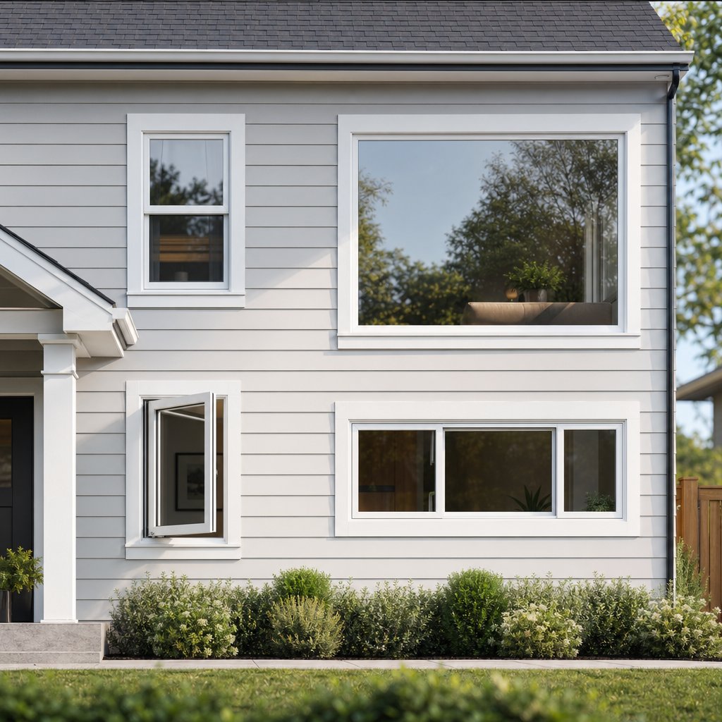
What Is an Aluminium Window Construction Detail
A leaking window rarely fails because of the glass or the frame alone. It fails at the junctions, the layers, the invisible transitions between materials that someone either drew correctly on paper or didn’t. That’s where the aluminium window construction detail comes in, and it’s the single document that separates a watertight installation from one that drips at the first horizontal rain event.
A construction detail is a scaled technical drawing or specification that maps every component layer and junction in a window assembly, including the frame profiles, sash, glazing unit, seals, thermal break, fixings, flashings, and the interface where the window meets the surrounding wall structure.
What a Construction Detail Actually Shows
Think of a window detail drawing as a cross-sectional slice through the complete assembly. It reveals elements you can’t see once the window is installed: the position of weather seals relative to the drainage plane, how the thermal break divides the aluminium structure into warm and cold zones, where packers sit beneath the frame, and exactly how flashings lap over one another. A good window section detail includes annotations for material types, dimensions, slope directions, and sealant placement. It’s not decorative. Every line carries performance intent.
Unlike a product brochure showing finished elevations, the detail focuses on what happens behind the visible surfaces. It communicates how water is managed, how air leakage is controlled, and how thermal energy moves through the assembly. For windows in aluminium, these drawings are especially critical because the aluminum window frame material conducts heat roughly 1,000 times faster than timber. That conductivity demands precision in how and where the thermal break sits, how fixings penetrate the profile, and how the frame connects to the wall without creating a cold bridge.
Why These Details Matter for Building Performance
Building performance lives or dies in the junctions. The wall might achieve excellent insulation values and the glazing unit might carry a strong U-value rating, but if the interface between the two leaks air or allows water in, none of that matters. Research from Building Science Corporation highlights that even high-performance glazing systems can be undermined by poor frame detailing and inadequate thermal breaks, with whole-window R-values dropping dramatically when frames aren’t properly resolved.
In the Australian context, where the National Construction Code (NCC) and NatHERS energy ratings increasingly demand higher thermal performance from the building envelope, getting the aluminium window design right at the detail level is non-negotiable. A compliant energy rating means nothing if condensation forms on interior frames during winter mornings in Melbourne, or if wind-driven rain penetrates a poorly sealed jamb in coastal Queensland.
Who Needs Aluminium Window Construction Details
Architects use them to coordinate the window with adjacent wall layers, waterproofing membranes, and cladding systems. Builders rely on them to install windows correctly on site, knowing where to place packers, how much clearance to leave for sealant joints, and which direction to slope the sub-sill. Homeowners benefit from understanding them because it demystifies why one quote costs more than another: the difference often lies not in the glass but in how thoroughly the installation junction has been resolved.
This matters more for aluminium than for timber or PVC precisely because of that thermal conductivity challenge. Timber frames are naturally insulating. PVC profiles use multi-chamber designs that inherently resist heat flow. Aluminium demands engineered solutions at every junction, and those solutions must be drawn, specified, and built with care. This article takes a building-science-first approach to each layer of the aluminium window assembly, explaining the reasoning behind every component so you can read, evaluate, and commission details that actually perform.
Anatomy of an Aluminium Window Frame Cross-Section
Reading a construction detail is straightforward once you know what each layer does. Picture slicing through a typical aluminium window frame at mid-height, from outside to inside. You’d pass through roughly nine distinct zones, each with a specific job in keeping water out, air sealed, and thermal energy where it belongs. Here’s what you’d encounter, layer by layer.
Exterior-Facing Components and Their Roles
The outermost surface of any aluminium window frame is the powder-coated or anodised aluminium face. This is the weather skin, the part exposed to UV, rain, salt air, and temperature swings. Directly behind it sits a series of components that manage moisture before it can reach the interior:
- Outer aluminium face: The extruded profile’s external leg, finished with a durable coating. It sheds bulk water and provides the first line of defence against wind-driven rain.
- Primary weather seal: A compression gasket (usually EPDM rubber) seated in a groove between the sash and the outer frame. This seal blocks the majority of air and water attempting to pass the sash-to-frame junction.
- Drainage channel: A shallow chamber milled or extruded into the frame profile, sitting just inboard of the primary seal. Any water that defeats the outer gasket collects here and drains to the exterior through weep slots at the sill.
- Thermal break zone: Polyamide strips (or a pour-and-debridge resin barrier) that physically split the frame aluminium profile into two separate halves, preventing conducted heat from travelling between outside and inside.
These four layers work as a system. The outer face deflects, the seal resists, the channel collects, and the thermal break isolates. Remove or compromise any single element, and the others can’t compensate.
The Glazing Pocket and How Glass Is Retained
Moving inward past the thermal break, you reach the glazing pocket, the rebate where the insulated glass unit (IGU) sits within the sash. The aluminium glass interface here is critical for both structural retention and long-term seal integrity. Two primary methods hold the glass in place:
Pressure-plate glazing uses an external aluminium plate, bolted through the frame’s outer leg, that clamps the glass against internal gaskets. This method is common in commercial aluminum window frames and curtain wall systems because it allows glass replacement from the exterior without disturbing internal finishes. The clamping force is distributed evenly, and a continuous gasket beneath the plate provides the weather seal.
Clip-bead glazing relies on a snap-fit aluminium bead that clicks into a channel on the interior face of the sash. The bead compresses a wedge gasket against the glass edge, holding the IGU securely. Residential aluminium window frames typically use this approach because it creates a cleaner interior sightline and simplifies factory assembly. The glazing bead can be removed with a flat tool if the glass ever needs replacing.
In both methods, the glass sits on setting blocks (small plastic or neoprene pads) positioned at quarter points along the sill of the sash. These blocks transfer the dead weight of the IGU into the sash frame without concentrating stress at a single point. Between the glass edge and the aluminium rebate, a secondary seal, often silicone or EPDM, prevents moisture from reaching the IGU’s edge spacer where it could cause premature seal failure and fogging.
Interior-Facing Elements and Finish Integration
The inner aluminium leg of the frame is the surface visible from inside the room. On thermally broken profiles, this internal section remains close to room temperature, which is what prevents condensation from forming on the frame during cold mornings. The key aluminum window components on this side include:
- Inner aluminium frame leg: Provides the structural fixing point for hardware (hinges, locks, handles) and houses the internal gasket groove.
- Secondary air seal: A fin-type or bulb gasket that sits between the inner sash face and the inner frame leg, creating the final barrier against air infiltration. This is distinct from the outer weather seal and forms what’s known as the “air line” in the assembly.
- Interior trim or reveal: Depending on the installation method, a timber reveal liner, plaster return, or aluminium sub-sill trim covers the junction between the window frame and the internal wall lining. This trim conceals the perimeter sealant and packer zone.
The interaction between the sash and the outer frame follows a straightforward logic: the sash closes against both the outer weather seal and the inner air seal simultaneously, creating a chambered zone between the two gaskets. This chamber is the pressure equalisation zone, and its behaviour under wind load determines whether water penetrates or drains harmlessly back outside. Understanding how these layers of a glass aluminium frame assembly relate to each other is what transforms a flat CAD drawing into actionable installation knowledge.
Each component described here appears as a distinct line or hatch pattern on a properly annotated detail drawing. The challenge isn’t identifying them individually; it’s understanding how they perform together at the three most failure-prone locations in any window installation: the head, the jamb, and the sill.
How Thermal Break Profiles Shape the Construction Detail
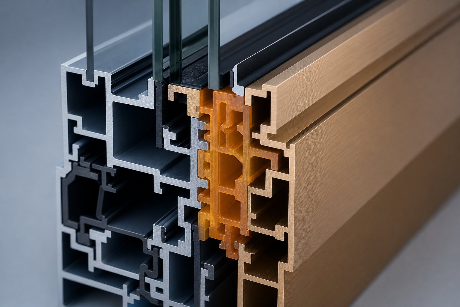
Of all the layers visible in a cross-section, one element dictates more performance outcomes than any other: the thermal break. It governs frame U-value, condensation behaviour, and even how fixings are positioned. Without grasping what happens at this zone, reading any aluminium window construction detail is essentially guesswork.
How Polyamide Strips Create a Thermal Barrier
Aluminium conducts heat roughly 1,000 times faster than timber. Left uninterrupted, a solid aluminium profile would act as a thermal highway, pulling warmth from your interior straight to the cold exterior face. The thermal break stops this by physically splitting the extrusion into two independent aluminium profiles joined only by low-conductivity polyamide strips.
These strips are made from PA66 reinforced with 25% glass fibre (PA66 GF25), a material with a thermal conductivity of just 0.30 W/(m·K) compared to aluminium’s 160 W/(m·K). Two manufacturing methods dominate. In the crimp-in approach, pre-formed polyamide strips are mechanically rolled into precision channels on the inner and outer aluminium halves, locking the assembly together. The pour-and-debridge method takes a different path: liquid polyamide resin is poured into a channel within a single extruded aluminum window frame profile, allowed to cure, and then the aluminium bridge between inner and outer legs is mechanically cut away, leaving the hardened polyamide as the sole connection.
Both methods achieve the same outcome: two thermally independent aluminium zones linked by material that barely conducts heat. The difference lies in manufacturing flexibility. Crimp-in strips suit complex window profiles with multiple chambers, while pour-and-debridge works well for simpler geometries where a continuous barrier is preferred.
Thermal Break Width and Its Effect on U-Value
The width of the polyamide barrier isn’t cosmetic. It directly controls how much heat crosses the frame. Wider breaks create a longer conductive path through a low-conductivity material, reducing the frame’s U-value proportionally. Contemporary aluminium window profiles range from entry-level systems with 14-20 mm breaks to high-performance configurations pushing 35-44 mm.
To put this in practical terms, a basic thermal break might deliver a frame U-value around 2.0-2.5 W/(m²·K). Increase the break width to 35 mm or beyond, and that figure drops to 1.2-1.8 W/(m²·K). Premium aluminum window extrusions designed for passive house certification push further still, achieving frame values below 1.0 W/(m²·K) through multi-chamber break geometries and foam-filled cavities within the polyamide zone itself.
For Australian projects chasing NatHERS compliance or improved WERS ratings, this width decision cascades through the entire detail. A wider thermal break demands deeper aluminium profiles, which changes rebate depths for glazing, affects hardware engagement, and alters how the frame sits within the wall reveal. Every millimetre of additional break width ripples outward through the construction detail at head, jamb, and sill.
Structural Considerations at the Thermal Break Zone
Here’s where things get interesting for builders and engineers. The thermal break isn’t just an insulation layer; it’s a structural connection carrying dead loads and wind loads between the inner and outer frame halves. Polyamide strips with 25% glass fibre reinforcement achieve tensile strengths of 90-120 MPa, but they still represent the weakest link in what would otherwise be a continuous metal section.
This has direct consequences for how fixings interact with aluminum window frame extrusions. Screws and brackets must anchor into the reinforcement chambers of the aluminium, never through the polyamide. Penetrating the thermal break creates both a structural weak point and a thermal bridge that defeats its purpose. On construction details, you’ll see fixing points called out specifically to avoid this zone, with packers positioned to transfer loads through the aluminium legs rather than across the insulating barrier.
At the sill, the thermal break must handle the dead weight of the glazing unit pressing down through setting blocks. At the jamb, it resists lateral wind suction. At the head, it carries the sash weight on hinged windows while managing deflection from the lintel above. Each location places different structural demands on the same material, which is why well-resolved details show different packer arrangements and fixing centres at each junction rather than a single repeated pattern.
Condensation resistance ties directly back to this zone as well. The Condensation Resistance Factor (CRF) measures how warm the interior frame surface stays relative to indoor conditions. A higher CRF means the interior aluminium leg remains above dew point temperature even during cold nights. Wider thermal breaks with lower conductivity keep that inner surface warmer, which is precisely why coastal homes in southern Victoria or elevated sites in the Tablelands benefit from specifying break widths at the upper end of what’s available. The thermal break width specified on your detail drawing isn’t just an energy efficiency number; it’s a condensation prevention strategy.
This structural and thermal interplay at the break zone explains why the thermal break appears on every serious aluminium window construction detail with its own dimension callout, material specification, and fixing exclusion zone. It’s the hinge point around which the rest of the detail is organised, and it behaves differently depending on whether you’re looking at a head, jamb, or sill section.
Head, Jamb, and Sill Details Explained
The thermal break divides the frame into warm and cold halves, but it’s the three perimeter junctions—head, jamb, and sill—that determine whether water stays outside or finds a path in. Each junction faces different gravitational, wind, and structural forces, which is why a single generic detail repeated at all three positions almost guarantees failure somewhere. An aluminium frame window demands distinct detailing at each location, tailored to what that junction actually has to resist.
| Junction | Primary Threat | Key Components | Critical Dimension |
|---|---|---|---|
| Head | Water cascading down the wall face above | Drip flashing, head reveal cavity, compressible foam or sealant, lintel deflection gap | Minimum 10 mm clearance for lintel deflection |
| Jamb | Lateral wind-driven rain and air leakage at frame edges | Fixing lugs or brackets, continuous weatherseal, packer shims, perimeter sealant with backing rod | 6-10 mm sealant joint width for movement tolerance |
| Sill | Pooled water with nowhere to drain; hydrostatic pressure from standing water | Sub-sill or sill pan with end dams and back dam, weep slots, sloped drainage surface, membrane flashing | Minimum 5-degree outward slope on sub-sill surface |
Head Detail and Drip Management
At the head, the construction detail’s primary job is intercepting water running down the wall face before it reaches the top of the frame. A drip flashing—typically a folded metal angle with a kick-out lip—projects beyond the wall plane above the window, breaking the surface tension of water film and throwing it clear of the frame below. This flashing integrates with the wall’s weather-resistant barrier (sarking or building wrap) in a shingled lap: membrane over the top of the flashing, flashing over the head of the frame.
The head reveal itself must accommodate lintel deflection. Steel or concrete lintels flex under load, and without a compressible gap between the lintel soffit and the top of the aluminium window framing, that load transfers directly into the frame. Details typically call for a 10-15 mm gap filled with closed-cell foam backer rod and sealed with a flexible sealant rated for at least 25% movement. Rigid packing here invites cracked glass and distorted sashes.
Jamb Detail and Lateral Sealing
Jamb junctions handle lateral forces. Wind-driven rain approaches horizontally, exploiting any discontinuity in the perimeter seal. The detail at this location shows fixing brackets or lugs screwed through the aluminium frame’s reinforcement chambers into the structural reveal—never through the thermal break zone—at centres typically between 300 mm and 600 mm depending on the wind classification.
Between fixings, packers shim the frame plumb and square within the reveal, maintaining a consistent sealant joint width around the perimeter. That joint needs a backing rod set to the correct depth (typically half the joint width) so the sealant stretches in two-point adhesion rather than tearing in three-sided adhesion. The weatherseal gasket running around the sash perimeter must maintain compression through the corner transition from head to jamb. If it’s cut and butt-joined at the corner rather than continuously welded or moulded, that corner becomes a leak point. For windows with aluminum frame construction exposed to coastal conditions, this lateral seal continuity is non-negotiable.
Sill Detail Including Drainage Slope and Weep Holes
The sill is where gravity concentrates every drop that makes it past the head and jamb. It’s also where the vast majority of water ingress failures occur in aluminium window installations. Research into aluminium windowsill flashing failures consistently finds that inadequate sill design and installation is the primary cause of water penetration into exterior wall systems, often going undetected until substantial damage has occurred to framing, linings, and insulation.
A properly resolved sill detail for windows with aluminum frame systems includes several non-negotiable elements. The sub-sill or sill pan sits beneath the window frame’s sill extrusion. It must slope outward at a minimum of five degrees so water cannot pool. It requires end dams at both sides—metal or formed membrane barriers that prevent water running laterally off the pan into the wall cavity. Behind the window, a back dam rises to a height determined by the window’s water tightness classification; higher performance ratings demand taller back dams because the system must contain more water before it drains.
Weep holes or slots in the outer face of the sill extrusion provide the exit path for any water collected within the frame’s drainage chamber. These openings are typically 5 mm x 25 mm, positioned at roughly 200 mm centres, and must remain unobstructed by render, mortar, or sealant. The Building Science Corporation emphasises that the bottom edge of any opening must remain free to drain to the exterior—sealing the sill flashing to the drainage plane below subverts the entire system.
Critical to this detail: anchoring the window through the horizontal surface of the sill pan creates fastener penetrations directly in the water collection zone. Where possible, the detail should specify fixings through vertical surfaces of the frame or through supplemental brackets that avoid puncturing the pan’s flat drainage plane. When penetrations through the horizontal sill are unavoidable—such as on concrete substrates—a fully bonded fluid-applied membrane beneath the sill provides secondary waterproofing around those fastener locations.
This concentration of risk at the sill explains why experienced specifiers spend more time on the bottom 100 mm of their aluminium window construction detail than on the head and jambs combined. Get the sill wrong, and water finds its way into the wall cavity quietly, accumulating damage behind finishes where it stays invisible until remediation costs multiply. Getting it right means every element—slope, dam height, weep placement, fixing method, and membrane lapping—works as an integrated drainage system rather than a collection of individual parts hoping for the best.
With the three junctions resolved on paper, the next question becomes practical: how do these details change depending on whether the window is face-fixed, set within a masonry reveal, or mounted on a structural sub-frame?
Installation Methods from Face-Fix to Structural Opening
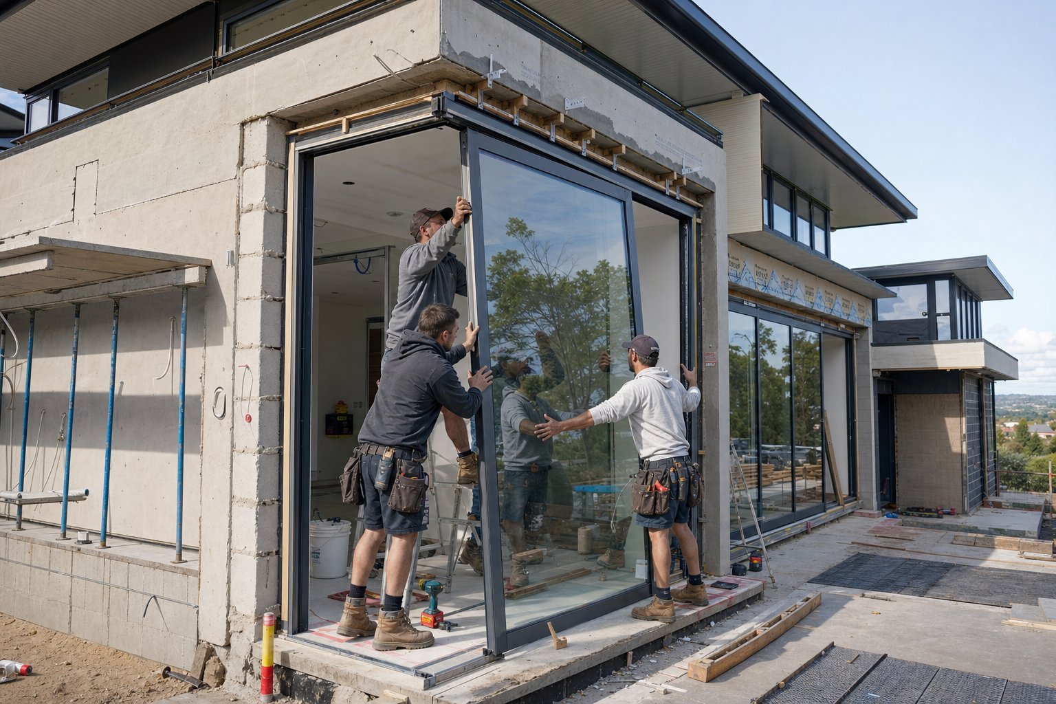
The answer depends entirely on the wall construction. A brick veneer home in suburban Melbourne presents a different fixing condition to a lightweight steel-framed commercial building wrapped in a ventilated rainscreen. The aluminium window construction detail shifts accordingly, because how you anchor the frame into the structure determines where packers sit, how flashings terminate, and whether the weatherseal line aligns with or drifts away from the wall’s weather-resistant barrier. Three primary methods cover the vast majority of Australian installations.
Face-Fixed Installation and When to Use It
Face-fixing is the most common approach for aluminium framed windows on standard residential builds. The window’s perimeter flange or fin sits flush against the external face of the wall framing, fixed directly through the cladding line. It’s straightforward, well understood by trades, and suits brick veneer, fibre cement sheet, and weatherboard cladding systems where the structural frame sits directly behind the cladding plane.
The trade-off is thermal. BRANZ research demonstrates that traditional face-fixed aluminium joinery positions the glazing and thermal break outside the wall insulation line, exposing the frame to a colder environment and allowing cold air to circulate around it. This can increase heat loss through the window junction noticeably. For projects where energy performance is paramount, face-fixing works best with wall systems where the insulation layer sits close to the exterior face, minimising the offset between glazing and insulation.
Reveal-Fixed Installation for Masonry Openings
When the structural opening is formed by masonry—double brick, concrete block, or rendered cavity brick—the window sits within the reveal rather than on the external face. Fixing lugs or brackets are screwed through the aluminium frame’s reinforcement chambers into the masonry jamb, head, and sometimes the sill substrate. The frame is shimmed plumb and square with plastic packers at each fixing point and midway between them.
This method positions aluminium frames for windows deeper within the wall thickness, which naturally improves the alignment between the glazing plane and the wall insulation. It also shifts flashing geometry. The head flashing must bridge the gap between the outer wall face and the recessed frame, directing water outward over the cladding below rather than relying solely on a surface-mounted drip. Perimeter sealant joints at the jamb become wider because the frame sits behind the wall face, demanding correct backing rod and bond-breaker detailing to accommodate structural and thermal movement.
Structural Sub-Frame Installation for Curtain Wall and Cladding Systems
Commercial projects, multi-storey residential, and builds with deep ventilated rainscreen cladding often require a structural sub-frame. Here, a steel or aluminium carrier frame is anchored to the primary structure first, and the window unit is then fixed into this sub-frame. The approach decouples the window from cladding movement, accommodates floor-to-floor deflection, and provides a consistent fixing substrate regardless of what sits behind the panels.
For larger alu systems—particularly those interfacing with curtain wall mullions or unitised facade panels—the sub-frame also houses the primary weatherseal and drainage zone. The aluminium window unit clips or bolts into the carrier, with gaskets compressed between the two forming the weather line. This means the construction detail must show two sets of junctions: the sub-frame to structure interface and the window to sub-frame interface. Missing either one results in a detail that looks complete on paper but leaks in practice. Window joinery for these applications demands tighter manufacturing tolerances because the gasket compression between window and carrier frame depends on precise dimensional coordination.
No single installation method suits all wall types. Specifying alum windows for a project without first understanding the wall build-up—its layers, insulation position, cladding depth, and structural substrate—is a recipe for misaligned details and site improvisation. The correct method is always the one that keeps the weatherseal continuous, the thermal break aligned with wall insulation, and the drainage path unobstructed.
Regardless of approach, the general installation sequence follows a consistent logic from opening preparation through to commissioning:
- Verify the structural opening dimensions, plumb, level, and substrate condition. Clean debris from the sill and confirm surfaces are sound for fixing and membrane adhesion.
- Install sill pan or sub-sill flashing with correct slope, end dams, and back dam. Integrate membrane laps with the wall’s weather-resistant barrier.
- Position the window unit in the opening on setting blocks. Shim with non-conductive packers at fixing points to achieve plumb, level, and consistent perimeter joint width.
- Anchor the frame through designated fixing points at specified centres, ensuring fasteners engage structural substrate—not cladding layers or the thermal break zone.
- Apply jamb and head flashings, lapping correctly over the sill membrane below and tucking under the wall wrap above to maintain a shingled drainage path.
- Install backer rod to the correct depth in the perimeter joint, then apply compatible sealant for two-point adhesion. Confirm no sealant blocks weep slots at the sill.
- Commission the window by checking hardware operation, gasket compression, drainage function (water test at sill weeps), and lock engagement. Record any defects for rectification before internal linings proceed.
Each step modifies slightly depending on whether the installation is face-fixed, reveal-mounted, or sub-frame supported—but the sequence itself holds. Skip or reorder any stage, and the weatherproofing integrity of even the best-designed aluminum framed windows can be compromised before the building is occupied.
Getting the frame secured and flashed is only half the battle. The real question is what happens once wind pressure acts on the sealed assembly: how does the frame’s internal drainage interact with the building junction’s waterproofing to keep water moving outward rather than inward?

Weatherproofing, Drainage, and Pressure Equalization Principles
Wind doesn’t just push air against a building. It pushes water. And the pressure difference between the windward face of a wall and the interior creates a driving force that can shove moisture through gaps smaller than a human hair. Seals alone can’t stop this. The physics demands a system that neutralises the pressure difference itself, while simultaneously draining any water that breaches the outer barrier. This is where the building science behind aluminium doors and windows gets genuinely elegant.
An aluminium window construction detail must illustrate two separate but connected drainage systems operating in concert: the frame’s internal drainage logic within the extruded profile, and the building junction’s weatherproofing at the perimeter where frame meets wall. Fail to resolve either one, and the other is eventually overwhelmed.
Pressure Equalization and Why It Prevents Water Ingress
Water doesn’t simply fall through openings in a window frame. It’s driven inward by air pressure differentials. During a storm, wind creates positive pressure on the building’s exterior face while the interior remains at lower pressure. That imbalance acts like a pump, pulling water through any micro-gap in the outer seal.
Pressure-equalised drainage design defeats this mechanism by allowing exterior wind pressure to communicate into a chamber between the outer and inner seals. When the pressure inside that chamber matches the pressure outside, the driving force disappears. Water sitting in the chamber is no longer being pushed inward—it simply rests there until gravity routes it downward and out through the sill.
The system works in four staged layers. First, an outer rain screen seal deflects the bulk of wind-driven rain and reduces the kinetic energy of water hitting the frame. Second, a pressure-equalised drainage chamber sits between the outer weather seal and the inner air seal, connected to the exterior via small ventilation slots that allow pressure to balance. Third, a sloped sill channel within the profile uses gravity to route collected water toward controlled exit points. Fourth, an inner air seal—typically a continuous EPDM gasket—forms the final thermal and acoustic barrier that, under normal conditions, never sees water at all.
The critical insight here: a weep hole by itself is not a drainage system. Without pressure equalisation, the same wind pressure that drives rain inward can also hold water captive inside the frame cavity or force it backward past the inner seal. The construction detail needs to show where the pressure-equalisation vents sit within the profile and confirm that the chamber geometry allows air movement without allowing water to bypass the drainage path.
Weep Slot Design and Drainage Channel Requirements
Every drop that enters the frame’s drainage chamber must exit before it accumulates enough to overflow inward. That exit path relies on weep slots—small openings in the outer face of the sill extrusion positioned at the lowest point of the internal drainage channel.
Effective weep design depends on several factors working together:
- Slot size and spacing: Industry-standard weep slots for aluminum doors and windows are typically 5 mm x 25 mm or larger, positioned at approximately 200 mm centres along the sill. Too few slots, or slots that are too small, restrict drainage flow below the rate of water entry during heavy events.
- Internal slope: The drainage channel within the frame profile must fall continuously toward the weep slots. A flat or back-sloping channel allows water to pond, accelerating debris build-up, biological growth, and eventual overflow. Well-engineered extrusions design the profile geometry around the drainage path rather than adding it as an afterthought.
- Obstruction prevention: Forensic analysis of fenestration failures consistently identifies blocked weep holes as a primary cause of water damage. Mortar droppings during bricklaying, render run-off, paint overspray, and even insect nests can seal these openings entirely. Weep covers—small mechanical flaps over the exterior slot—help prevent blockage while still allowing water to drain under gravity.
- Height differential: The internal water level must be higher than the external exit point for positive drainage pressure. A 50-75 mm rise between the internal collection zone and the weep slot creates sufficient head to drive water outward even in calm conditions.
At coupler joints—where two frame sections meet at a mullion or transom—the waterproof line must remain continuous. Installation documentation for most aluminium window systems specifies sealant or gasket detailing at these junctions to prevent water bypassing the drainage chamber at the join. A construction detail that shows the frame profile but ignores coupler waterproofing is incomplete for any aluminum window wall configuration wider than a single unit.
Perimeter Sealant Joints and Weatherproofing Continuity
Beyond the frame’s internal drainage, a second moisture management system operates at the perimeter junction where the window meets the wall. This is the building junction’s weatherproofing, and it follows different rules to the frame’s own drainage logic.
The perimeter sealant joint serves as the primary barrier between the exterior environment and the wall cavity. Getting this joint right demands attention to three things: sealant chemistry, joint geometry, and substrate preparation.
Sealant selection for aluminium window perimeters typically comes down to two options. Polyurethane sealant is the workhorse choice—paintable, tough, excellent adhesion to both aluminium and masonry substrates, and cost-effective across long runs. Its weakness is UV degradation, so exposed joints facing north or west benefit from paint protection or an MS polymer alternative that combines polyurethane’s paintability with silicone’s UV resistance. Silicone suits glass-to-frame joints and curtain wall applications where the bead stays exposed but doesn’t need painting.
Backing rod is non-negotiable. A closed-cell foam rod, sized approximately 25% larger than the joint width, is pressed into the gap before sealant application. It controls sealant depth (the depth should equal half the width for joints over 12 mm) and prevents three-sided adhesion—the single most common cause of perimeter sealant failure. When sealant bonds to both sides of the joint and the back surface simultaneously, it cannot stretch as the building moves. The inevitable result is adhesion failure or cohesion tearing, and then water finds its path in. For shallow joints where a backer rod won’t fit, bond-breaker tape across the back of the joint achieves the same two-sided adhesion geometry.
Continuity matters as much as chemistry. The perimeter sealant line must run unbroken around the entire window frame, transitioning smoothly at corners without gaps or cold joints. Where the sill membrane flashing meets the jamb wrap, and where the jamb wrap tucks under the head flashing, every lap must maintain the drainage principle: water always sheds outward and downward, never pooling against a sealed edge.
For aluminium doors windows configured as multi-panel assemblies or stacking sliders, the number of perimeter joints and coupler connections multiplies. Each additional junction is another potential failure point where the two drainage systems—frame internal and building junction—must coordinate. The construction detail for these larger assemblies needs to show every coupler cross-section and every transition between frame drainage and wall drainage, not just the typical mid-frame section that appears on most specification sheets.
When both systems work as designed, water follows a predictable path: deflected at the outer seal, collected in the pressure-equalised chamber, drained through sloped channels to weep slots, and expelled to the exterior. Any water reaching the perimeter junction encounters a properly tooled sealant bead backed by membrane flashings that direct it outward. The question remaining is how performance standards quantify this behaviour—and how testing classifications translate these principles into the specific dimensions, fixing centres, and seal configurations that appear on a compliant detail drawing.
Performance Standards That Govern Aluminium Window Details
Drainage principles and pressure equalisation explain how water is managed. Performance standards quantify how much water, wind, and air a given detail must handle before it’s considered compliant. In Australia, commercial aluminium windows and residential units alike must satisfy measurable thresholds for air permeability, water tightness, and wind load resistance—and each threshold imposes specific physical requirements on the construction detail itself.
How AS 2047 and EN 14351-1 Govern Detail Decisions
Under AS 2047, every aluminium window installed in Australia must demonstrate structural adequacy against design wind pressures specific to the building’s location and height, resist water penetration at a test pressure derived from that wind classification, and limit air infiltration below defined thresholds. Compliance is verified through testing at NATA-accredited laboratories and evidenced by a performance label on the frame itself. The standard is referenced directly in the National Construction Code, making it a legal baseline rather than a voluntary benchmark.
Europe’s EN 14351-1 takes a classified approach. Rather than pass/fail against a single location-specific pressure, it assigns products to performance classes—Class 1A through 9A for water tightness, Class 1 through 4 for air permeability, and Classes 1 through 5 for wind resistance. Specifiers select the appropriate class for their project exposure, and the manufacturer demonstrates compliance to that tier. This modular approach suits architectural aluminum windows destined for varied climates across different countries.
North America’s AAMA/WDMA/CSA 101 standard (now administered by FGIA) classifies fenestration into four performance grades—R (Residential), LC (Light Commercial), CW (Commercial), and AW (Architectural). Each grade sets progressively stricter minimums for allowable air leakage and water test pressure. Architectural grade (AW) demands the tightest air infiltration limit and highest water resistance, reflecting its use in high-rise and exposed commercial aluminum window details.
Air, Water, and Wind Performance Classes Explained
| Standard | Region | Air Permeability | Water Tightness | Wind Load | How It Affects the Detail |
|---|---|---|---|---|---|
| AS 2047 | Australia | Maximum infiltration rate at design pressure (location-specific) | Must resist 100% of serviceability wind pressure without leakage | Must withstand ultimate limit state wind pressure without failure | Higher wind zones demand closer fixing centres, heavier frame sections, and larger structural glazing beads |
| EN 14351-1 | Europe | Classes 1-4 (tested at 150-600 Pa) | Classes 1A-9A (tested at 0-600 Pa) | Classes 1-5 (tested at 400-2000 Pa) | Higher classes require more sophisticated multi-stage drainage, wider thermal breaks for condensation control, and deeper gasket engagement |
| AAMA/WDMA/CSA 101 (FGIA) | North America | R/LC/CW: 0.30 CFM/ft² at 1.57 psf; AW: 0.10 CFM/ft² at 6.24 psf | R: 2.92 psf; LC: 3.76 psf; CW: 4.59 psf; AW: 8.15 psf | Design pressure varies by grade and application | AW-class aluminium commercial windows need three times the air seal performance of residential grade, driving double-gasket configurations and tighter manufacturing tolerances |
The pattern across all three standards is consistent: as performance class increases, the construction detail must incorporate more robust drainage, tighter sealing, and stronger anchorage. A window rated for a sheltered single-storey suburban location carries fundamentally different detail requirements than aluminum double glazed windows specified for a ten-storey coastal apartment in northern Queensland.
Translating Performance Requirements Into Physical Details
Performance numbers on a test certificate only mean something if they translate into physical reality on site. Here’s how the key parameters shape what appears on the construction detail drawing:
- Higher water tightness class demands deeper pressure-equalisation chambers within the frame, more weep slots at the sill, taller back dams on sub-sill pans, and multi-stage seal configurations. A Class 9A window under EN 14351-1 will show a markedly different sill cross-section than a Class 3A product—more chambers, more seals, more controlled drainage paths.
- Higher wind load rating requires closer fixing centres (often 200-300 mm rather than 450-600 mm), heavier aluminium section weights, deeper screw engagement into structural substrates, and reinforced corner connections within the frame. The detail must call out fixing type, depth, and centres explicitly.
- Lower air permeability class pushes the detail toward double or triple gasket seal lines, tighter hardware engagement tolerances, and more demanding sash-to-frame compression requirements. Gasket material and geometry become specification items rather than afterthoughts.
For Australian projects, AS 2047 ties all three parameters to the building’s specific wind region and terrain category. A project in Wind Region A (most of southern Australia) faces lower structural and water pressures than one in Region C (cyclone-prone northern coastline). The construction detail shifts accordingly—not just in frame section size, but in fixing methodology, drainage capacity, and seal redundancy. Specifying commercial aluminium windows without checking that the documented detail matches the required performance class is a compliance gap waiting to surface during certification or, worse, during the first major storm event.
These standards create the measurable benchmarks. But benchmarks only matter if the installation matches the tested configuration. The gap between a laboratory-tested specimen and a site-installed window is where most failures actually occur—a subject of specific, preventable construction detail errors.
Common Construction Detail Failures and How to Prevent Them
Laboratory test results prove a window system works. Site conditions prove whether anyone read the detail drawing before picking up a drill. The gap between tested performance and installed reality is where most aluminium window failures originate—not from defective products, but from construction errors that violate the principles built into the detail. Five failure modes account for the overwhelming majority of water ingress and thermal performance complaints in Australian aluminium window installations.
Sub-Sill Failures and Drainage Errors
The sill carries more risk than the head and jambs combined, and the sub-sill flashing is where that risk concentrates. Investigation into aluminium windowsill failures consistently identifies the same pattern: water penetrates quietly into the wall cavity below the window, absorbed by framing and linings for months or even years before visible damage appears. By the time staining shows on interior surfaces, structural decay may already be advanced.
The root causes are predictable. A sub-sill pan installed flat rather than sloped allows water to pond indefinitely. End dams that are too short or poorly sealed at their corners let water run laterally off the pan into the wall cavity. Fasteners driven vertically through the horizontal drainage surface of the pan create penetrations directly in the wet zone—and dabs of sealant over screw heads routinely debond under thermal cycling, leaving open paths for moisture.
Shop-welded end dams provide a more robust solution than field-assembled ones, because the welds can be tested for watertightness before the assembly leaves the factory. Where penetrations through the horizontal sill surface are unavoidable, a fully bonded fluid-applied membrane beneath the pan adds secondary protection. Mock-ups tested on-site before full installation proceeds remain the most reliable way to verify that the drainage slope, dam height, and weep alignment actually function as drawn.
Thermal Bridging Through Fixings and Packers
A thermally broken aluminium profile achieves nothing if the installation creates an alternative conductive path around the break. This happens more often than specifiers expect. The most common culprit: continuous aluminium or steel packers placed beneath the frame at fixing points, bridging directly from the cold outer leg to the warm inner leg. A 3 mm aluminium packer spanning the full profile depth bypasses the polyamide thermal break entirely, creating a localised cold spot that drops the interior frame surface below dew point.
The physics is unforgiving. Thermal bridges bypass insulation, pulling heat outward and creating condensation-prone zones that compromise both energy performance and occupant comfort. In an aluminium window frame, the thermal break exists specifically to interrupt heat flow—so any material bridging across that zone defeats the purpose of the system.
Prevention requires non-conductive packing materials—typically high-density polyethylene (HDPE) or engineered nylon shims—placed only under the inner or outer aluminium leg rather than spanning the full frame depth. Fixing screws must engage the structural chambers of the aluminium profile without passing through the polyamide zone. The construction detail should call out packer material, position, and maximum span explicitly. If it doesn’t, the installer defaults to whatever’s in the toolbox—and that’s usually metal.
Sealant and Weatherseal Discontinuity Problems
Two distinct failure modes operate here, and both stem from the same issue: broken continuity in what should be an uninterrupted barrier.
Perimeter sealant without backing rod is the first. When sealant fills the full depth of the gap between frame and wall without a backer rod controlling its profile, three-sided adhesion results. The sealant bonds to both jamb faces and the back of the joint simultaneously, leaving no capacity to stretch when the building moves. Thermal cycling, structural settlement, or wind deflection tears the bead within a few seasons. The fix is straightforward—a closed-cell backer rod sized 25% larger than the joint width, pressed to the correct depth before sealant application, creating the two-point adhesion geometry that allows the bead to flex without failing.
Discontinuous weatherseal gaskets at frame corners represent the second mode. The EPDM or silicone gasket running around the sash perimeter must transition through 90-degree corners at each head-to-jamb and jamb-to-sill junction. If the gasket is simply cut and butt-joined at these corners rather than continuously welded or vulcanised, a micro-gap forms under compression cycling. Wind-driven rain exploits these gaps ruthlessly, particularly at the lower corners where water naturally gravitates. Quality aluminium window manufacturers address this through factory-welded corner gaskets or continuous moulded seal profiles that eliminate butt joints entirely.
A final failure mode compounds all others: blocked weep holes. Mortar droppings from bricklaying above, render overspray, paint splash, or even insect nests can seal the weep slots that allow the frame’s internal drainage chamber to evacuate water. Once blocked, the chamber fills during rain events until water overflows past the inner air seal and into the building. Prevention demands physical protection during construction (temporary tape covers removed at commissioning) and periodic inspection as part of building maintenance.
Each of these failure modes shares a common thread: they’re all preventable at the detail stage. The following list summarises the five critical failures, their root causes, and the specification response that eliminates each one:
- Flat or back-sloped sub-sill pan: Root cause—installer fails to verify slope direction or relies on the structural substrate being level. Prevention—specify minimum 5-degree outward fall on all sub-sill assemblies, verify with spirit level during installation, and mandate mock-up testing for projects with more than ten openings.
- Conductive packers spanning the thermal break: Root cause—no material specification for packers on the detail drawing, leading to default use of metal offcuts. Prevention—specify non-conductive HDPE or nylon packers and indicate their position relative to the thermal break zone on the section drawing.
- Three-sided sealant adhesion: Root cause—backing rod omitted to save time, or joint depth too shallow for rod insertion. Prevention—specify closed-cell backer rod diameter and set depth on the detail; for shallow joints under 10 mm, specify bond-breaker tape.
- Butt-jointed corner gaskets: Root cause—field-cut gaskets installed without vulcanised corner pieces. Prevention—specify factory-welded or moulded continuous corner gaskets as a procurement requirement, not an optional upgrade.
- Blocked weep slots: Root cause—construction debris accumulates during bricklaying, rendering, or painting phases. Prevention—specify temporary protective covers over weep slots during construction, with mandatory removal and function testing at commissioning.
The common denominator across all five failures is the distance between what the detail drawing specifies and what actually gets built. Working with aluminium windows manufacturers who provide comprehensive installation details, system-specific guidance, and site support significantly reduces this gap. Manufacturers like MEICHEN, who supply complete technical documentation alongside their aluminium window systems, give installers clear reference points for packer placement, sealant methodology, and drainage verification—turning the detail drawing from an abstract document into a buildable instruction set.
Choosing an aluminum windows manufacturer that treats installation guidance as part of the product—not an afterthought—is one of the most effective risk-reduction strategies available to builders and project teams. When the aluminium window supplier provides tested details matched to their specific profiles, tolerances, and hardware, the guesswork that causes these five failures largely disappears.
Preventing failures is half the equation. The other half is knowing how to evaluate competing window systems before committing to a product—because not all aluminium window companies document their details to the same standard, and the quality of that documentation directly predicts installation success.

Selecting the Right Aluminium Window System for Your Project
Documentation quality separates aluminium window systems that perform from those that leak. A manufacturer might produce excellent extrusions with precision thermal breaks, but if the technical library doesn’t tell installers how to detail those profiles at a masonry jamb or a timber-framed sill, the product’s potential never translates into on-site reality. Evaluating a system means reading beyond brochure photography and into the construction details themselves.
Evaluating Manufacturer Technical Documentation
Strong technical documentation includes more than a single typical cross-section. Look for the following when assessing whether a manufacturer’s detail library is genuinely buildable:
- Junction-specific details: Separate drawings for head, jamb, and sill—ideally for multiple wall types (brick veneer, lightweight frame, rendered masonry, and concrete). A system with only one generic section forces installers to improvise at every non-standard condition.
- Installation sequences: Step-by-step guidance covering sub-sill preparation, packer placement, fixing methodology, flashing integration, and sealant specification. The best documentation includes torque values for fixings and compression dimensions for gaskets.
- Performance test reports: NATA-accredited test certificates showing the exact configuration tested—not just a headline result, but the fixing centres, seal types, and glass thickness used during testing. If your site condition deviates from the tested setup, the certificate may not apply.
- Thermal modelling data: Frame U-values and condensation resistance factors calculated for the specific profile, not extrapolated from a different product in the range. WERS data matched to glazing combinations helps verify NatHERS compliance before the energy assessor runs their model.
- CAD and BIM files: Downloadable detail drawings in formats that architects and drafters can integrate directly into project documentation. Systems that provide DWG or Revit families reduce coordination errors between design and construction teams.
A manufacturer that can’t produce junction-specific details for common Australian wall types is signalling something important: either they haven’t tested those conditions, or they expect the builder to figure it out. Neither outcome protects your project from the failure modes described earlier.
Matching System Grade to Project Requirements
Residential aluminium windows and commercial-grade systems serve fundamentally different structural and performance demands. The distinction isn’t just about price—it’s about section depth, hardware capacity, wind load rating, and long-term cycle durability. Choosing the wrong grade creates problems that no amount of careful installation can resolve.
Residential systems suit single-storey and double-storey homes with standard opening sizes, moderate wind zones (typically Region A or B under AS 4055), and conventional hardware loads. They use lighter aluminium sections with narrower sightlines, making them ideal for projects where slimline aluminium windows deliver the clean aesthetic homeowners want without over-engineering the structure. These profiles work well for awning, casement, and sliding configurations in openings up to roughly 2,400 mm wide and 1,800 mm tall, depending on the system.
Commercial systems step up when the project demands larger spans, higher wind ratings, heavier glazing units, or more intensive operational cycles. Hotels, office towers, multi-storey apartments, and buildings in cyclone-prone regions of northern Queensland or the NT typically require commercial-grade aluminium sections with deeper profiles, reinforced corner cleats, and heavy-duty multi-point locking hardware rated for tens of thousands of operating cycles.
Bespoke aluminium windows for luxury residential projects sometimes blur this boundary. A three-storey coastal home with floor-to-ceiling glazing panels and high wind exposure might need commercial section depths paired with residential-grade finishes and hardware aesthetics. This is where manufacturers offering both grades within a coordinated system add genuine value—allowing specifiers to pick the structural performance they need without compromising on visual refinement.
MEICHEN’s aluminium window range illustrates this approach, providing residential and commercial systems with custom options, performance-tested configurations, and project integration support tailored to Australian builds. Their product library spans window types from standard awning and sliding units through to custom aluminium windows sized for large architectural openings—available in a range of colours including aluminium black windows that suit contemporary facades. For project teams weighing system grade against budget and aesthetic goals, exploring a manufacturer’s full range in one place simplifies the specification process considerably.
Custom Options and Project-Ready Integration
Beyond grade selection, several evaluation criteria determine whether a system integrates smoothly into your specific project or creates coordination headaches downstream:
- Colour and finish range: Powder coat colour options matter for design continuity. Black aluminium windows remain a dominant choice for modern Australian homes, but the system should offer the full range of standard and custom colours without extended lead times that disrupt construction programs. Confirm whether the coating meets AS 3715 for durability in your exposure zone.
- Hardware compatibility: Locks, stays, hinges, and rollers should be system-matched by the manufacturer rather than sourced separately. Mismatched hardware creates engagement issues that compromise seal compression and operational longevity.
- Glazing thickness range: The rebate depth must accommodate the insulated glass unit thickness your energy assessment requires. A system limited to 20 mm IGUs won’t accept the 24 mm or 28 mm double-glazed units increasingly specified for NatHERS 7-star compliance in southern climate zones.
- Seal longevity and replacement: Ask whether gaskets are proprietary or standard EPDM profiles. Proprietary seals tied to a single supplier create maintenance risk if that supplier exits the market. Standard profiles remain available through multiple channels for decades.
- Drainage design transparency: The manufacturer should clearly document weep slot sizes, drainage channel geometry, and pressure-equalisation chamber configuration for their specific profiles. If this information isn’t published, it’s difficult to verify that the system’s drainage logic matches the performance certificate.
- Cyclone and bushfire compliance: For projects in BAL-rated zones or cyclone regions, confirm the system holds specific test evidence for those conditions—not just a general claim of suitability. AS 2047 compliance alone doesn’t guarantee BAL-40 or Region C wind performance without explicit testing to those parameters.
Selecting the right system early—before design development locks in opening sizes and wall build-ups—prevents the costly rework that follows when a preferred window can’t meet the structural or thermal requirements discovered later in documentation. The aluminium window construction detail is only as reliable as the system it describes, and the system is only as trustworthy as the documentation backing it up. Start with the technical library. If the details are thorough, tested, and specific to Australian conditions, the rest of the specification follows naturally.
Frequently Asked Questions About Aluminium Window Construction Details
1. What is included in an aluminium window construction detail?
An aluminium window construction detail is a scaled cross-sectional drawing that maps every component layer and junction in the window assembly. It includes the outer aluminium face, primary weather seal, drainage channel, thermal break zone, glazing pocket with retention beads, inner air seal, and the interface where the frame meets the surrounding wall structure. It also specifies dimensions, material types, slope directions, sealant placement, fixing centres, and flashing laps at head, jamb, and sill junctions. A complete detail shows both the frame’s internal drainage system and the building junction weatherproofing as two connected but separate systems.
2. Why do aluminium windows leak at the sill more than other locations?
Sill junctions concentrate every drop of water that gravity draws down from the head and jambs above. Unlike the head or jamb, the sill must resist hydrostatic pressure from pooled water rather than just deflecting wind-driven rain. Common failures include flat or back-sloped sub-sill pans that allow ponding, inadequate end dams that let water escape laterally into the wall cavity, and fasteners driven through the horizontal drainage surface creating unsealed penetrations. These issues often go undetected for months because water absorbs into framing and linings behind finished surfaces before visible damage appears.
3. How does a thermal break work in an aluminium window frame?
A thermal break physically splits the aluminium extrusion into two independent halves—an exterior-facing section and an interior-facing section—connected only by low-conductivity polyamide strips reinforced with 25% glass fibre. These strips have a thermal conductivity of approximately 0.30 W/(m·K) compared to aluminium’s 160 W/(m·K), effectively interrupting the conductive heat path through the frame. The width of the thermal break directly affects the frame’s U-value: wider breaks of 35-44 mm can achieve frame U-values of 1.2-1.8 W/(m·K), while narrower 14-20 mm breaks typically deliver 2.0-2.5 W/(m·K). This zone also determines condensation resistance on interior frame surfaces during cold conditions.
4. What causes sealant failure around aluminium window perimeters?
The primary cause of perimeter sealant failure is three-sided adhesion, which occurs when sealant is applied without a backing rod and bonds to both joint faces plus the back surface simultaneously. When the building moves through thermal cycling or structural settlement, the sealant cannot stretch because it is restrained on three sides, leading to adhesion failure or cohesion tearing. Prevention requires inserting a closed-cell foam backer rod sized 25% larger than the joint width before applying sealant, creating two-point adhesion that allows the bead to flex. For joints shallower than 10 mm, bond-breaker tape across the back achieves the same geometry.
5. How do I choose between residential and commercial grade aluminium window systems?
The choice depends on opening size, wind zone classification, glazing weight, and operational cycle demands rather than simply building type. Residential systems suit single and double-storey homes in moderate wind zones (typically Region A or B under AS 4055) with standard openings up to roughly 2,400 mm wide. Commercial systems are necessary for larger spans, higher wind ratings, heavier insulated glass units, or buildings requiring tens of thousands of hardware operating cycles. Some projects—such as multi-storey coastal homes with floor-to-ceiling glazing—need commercial structural performance paired with residential-grade aesthetics. Manufacturers offering both grades within a coordinated system allow specifiers to match structural performance to the project without compromising visual refinement.
More Window & Door Guides