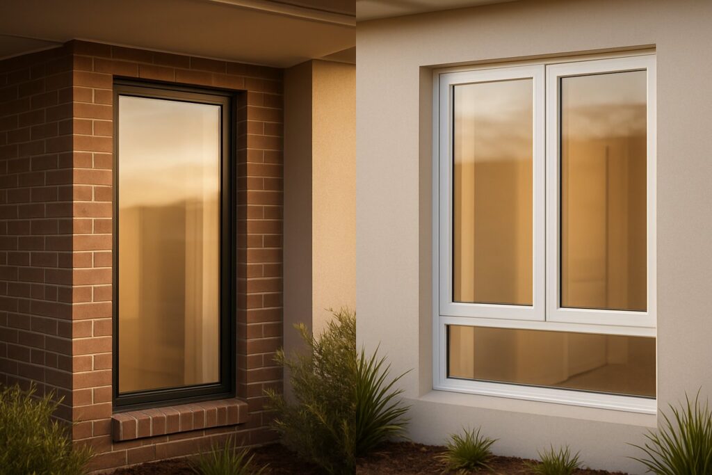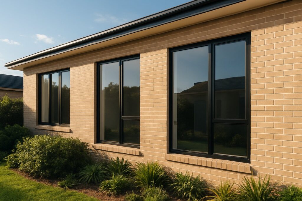
What Is an Aluminium Window Head Detail and Why It Matters
An aluminium window head detail is the horizontal junction at the top of a window frame where the aluminium profile meets the wall structure above. It encompasses the lintel support, weatherproofing layers, thermal insulation continuity, and sealant interfaces that together prevent water from entering the building at this critical point. When any one of these elements fails or is poorly coordinated, moisture finds a path inside.
What the Head Detail Actually Is
Picture the topmost horizontal member of your window frame. That aluminium section doesn’t just sit in the opening — it forms a complex interface between the building’s structure and its protective envelope. The window head detail includes the lintel overhead (carrying the wall load), the flashing or cavity tray that deflects water, insulation that maintains thermal continuity, and the sealant lines that tie everything together. It’s not visible from the street, yet it’s where most window leaks originate.
Unlike the sill or jamb, the head faces a unique challenge: gravity drives water directly onto it from the wall above. Every window detail drawing places the head junction as the primary defence against downward water flow, and for good reason. A guide published by ArchDaily notes that the brickwork or blockwork above every opening requires lintel support, and that lintels filled with EPS insulation or thermally broken lintels further reduce thermal bridging at this junction.
Why Correct Head Detailing Matters
Get the window head detail wrong and you face a cascade of problems: water ingress staining interior walls, thermal bridging that drives condensation and mould growth, structural cracking as lintels shift under load, and premature sealant breakdown from movement the joint wasn’t designed to accommodate. These aren’t hypothetical failures — they’re the most common defects found in post-construction inspections across Australian residential builds.
The head detail is not a single component but an integrated weathering system. Lintel, flashing, frame, sealant, and insulation must coordinate as one assembly. A weakness in any single layer compromises the entire system above the window.
Most available resources either stay at a high conceptual level or dive straight into manufacturer-specific PDF details with no explanation of why each layer exists. The window details that follow in this article bridge that gap — walking through each component, each decision, and each failure mode so you can identify exactly where your head junction is letting water through.
Anatomy of the Aluminium Window Head Assembly
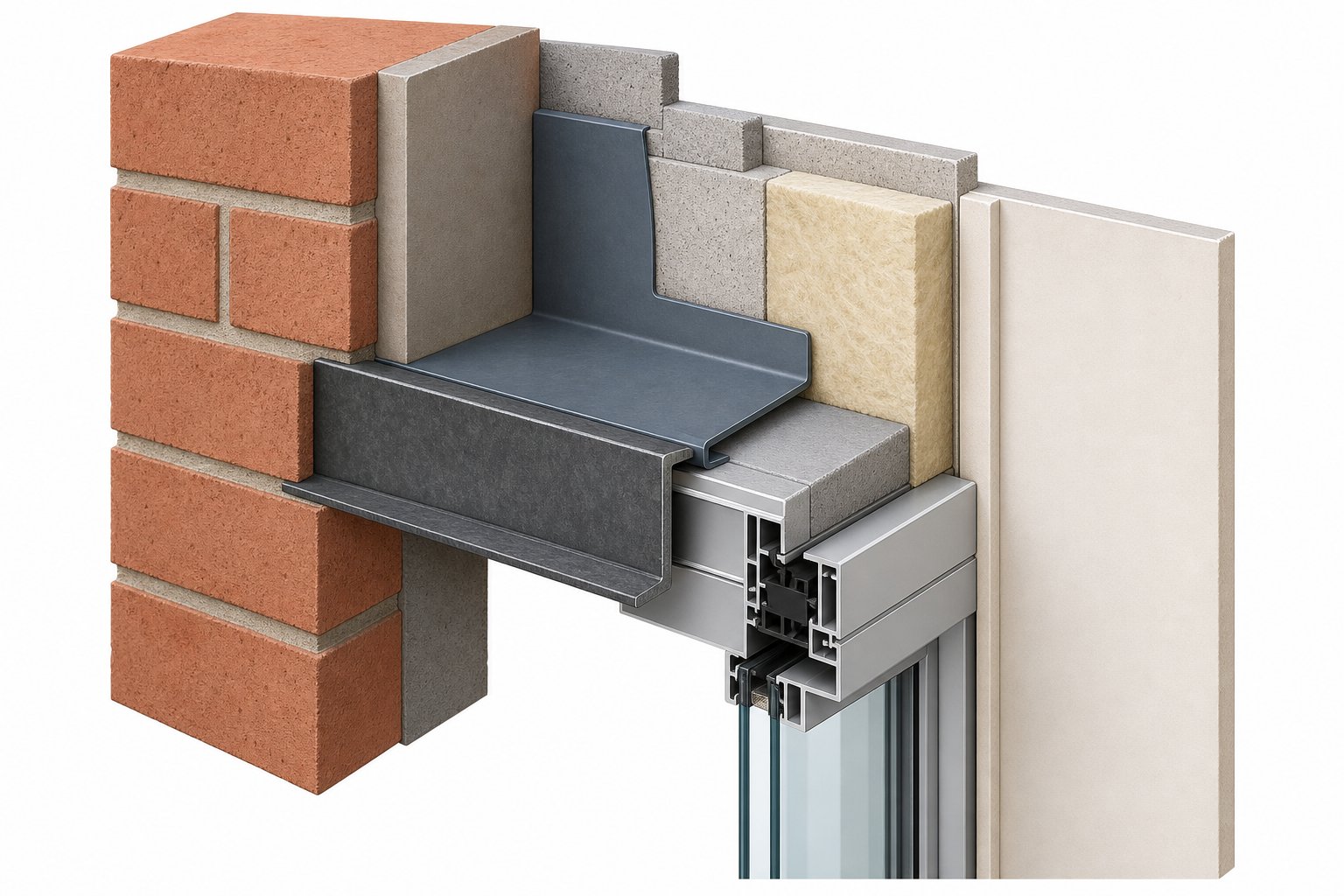
Knowing that the head detail is an integrated system is one thing. Understanding exactly which layers make up that system — and where each one sits relative to the next — is what separates a weathertight installation from one that leaks within two winters. A window frame detail at the head typically involves seven or more distinct components, each performing a specific role and each depending on correct placement relative to its neighbours.
The clearest way to think about this assembly is from the outside in, layer by layer. Every component you encounter moving from the external face of the wall toward the interior plays a defined part in structure, weathering, or thermal performance. Here’s the full picture.
Structural Support Layer
The lintel sits at the top of the assembly. Its job is straightforward but critical: carry the weight of the masonry, timber, or cladding above the opening and transfer that load sideways into the wall structure on either side. The aluminium frame itself is never designed to bear wall loads — it carries only its own weight and the glazing. Every gram of masonry must bypass the frame entirely.
Minimum end bearing for steel lintels is 150mm on each side, bedded on mortar and levelled along its length and across its width. For precast concrete lintels, bearing requirements are similar but vary by span — longer openings demand more bearing surface. The lintel must be installed level because any tilt affects the cavity tray above and the head clearance below. If it’s not level, water pooling on the cavity tray becomes inevitable.
In Australian residential construction, steel angle lintels and galvanised pressed-steel lintels are common in brick veneer and full masonry walls. The lintel profile depth determines how much vertical space is consumed above the window, directly affecting the available head clearance for the aluminium frame below.
Weathering and Drainage Layer
Directly above the lintel (or integrated with it in some proprietary systems), the cavity tray or head flashing forms the primary moisture barrier. Its purpose is to catch any water that penetrates the outer leaf of the wall and redirect it back outside before it reaches the window frame or interior structure.
The cavity tray must rise a minimum of 150mm from the outer leaf to the inner leaf, supported along its length to prevent sagging. It should span the full length of the lintel and include sealed stop ends at each end — without these, moisture simply runs off the tray edges and drops into the cavity where it eventually finds the frame head or internal lining.
Weep holes in the outer leaf immediately above the cavity tray allow collected water to drain outward, positioned at maximum 900mm centres. Open perpend joints or proprietary weep vents serve this purpose. Keep in mind that mortar droppings are the most common cause of blocked drainage paths. If debris dams the tray during construction, the entire weathering layer is compromised before the building is even occupied.
Frame Interface Layer
Below the lintel soffit sits the aluminium head profile itself. This is where the window frame detail becomes specific to the system manufacturer, but the principles are universal. The frame head must not touch the lintel. A minimum head clearance of 5–10mm is standard practice, allowing for structural deflection, thermal expansion, and construction tolerance.
Packers — typically non-compressible plastic or nylon — fill this gap at regular centres (usually no more than 450mm apart) to hold the frame in position during fixing. The remaining gap receives a compressible backing rod and sealant. On the external face, a weather seal (neutral-cure silicone or compatible sealant) provides the primary rain defence at the frame-to-structure junction. On the internal face, an air seal prevents warm moist interior air from reaching the cold zone behind the frame — a detail often overlooked but essential for condensation control.
Thermally broken aluminium profiles incorporate a polyamide strip within the head section, separating the external aluminium face from the internal face. This reduces heat conduction through the frame and lowers condensation risk on the interior head profile. Insulation must close the cavity at the head, lapping over the lintel and connecting to the broader wall insulation to avoid a thermal gap.
Complete Assembly: Exterior to Interior
When you examine a window detail drawing or cross-section through the head, the components should appear in this order:
- External masonry, cladding, or render finish (outer face of wall)
- Lintel — bearing on structure, spanning the opening
- Cavity tray or DPC flashing — rising minimum 150mm with sealed stop ends
- Weep provision — open perpend or proprietary weep vents in the outer leaf above the tray
- Cavity insulation closure — maintaining thermal continuity over the lintel
- External weather seal — between frame head and lintel or reveal
- Aluminium frame head profile — with or without thermal break, held off lintel soffit by packers
- Backing rod and sealant — filling the head clearance gap
- Internal air seal — preventing moisture-laden air reaching the cold side of the assembly
- Internal plasterboard lining, head trim, or reveal finish
If you’re working from a window frame diagram or CAD detail, trace each of these layers in sequence. Any break in the chain — a missing stop end, a compressed packer that eliminates the head clearance, insulation that stops short of the lintel — creates a weak point. And water, being relentless, will find it.
With the full anatomy mapped out, the next question becomes: how does the type of lintel you select reshape this entire assembly? The answer varies significantly depending on whether you’re working with a simple steel angle, a deep precast unit, or a proprietary cavity lintel with integrated insulation.
How Lintel Type Shapes Your Window Section Detail
The lintel you select doesn’t just carry load — it dictates the entire geometry of the head assembly below it. Change the lintel and you change the setback, the clearance, the flashing arrangement, and how the aluminium frame is restrained. Every window section detail you produce on a drawing is, at its core, a response to the lintel sitting above.
Three lintel types dominate Australian residential and commercial construction when aluminium windows are involved. Each one creates a fundamentally different head configuration.
Steel Angle Lintels and Their Impact on Head Geometry
Steel lintels are the most common choice in brick veneer and masonry cavity wall construction across Australia. Pressed galvanised steel lintels span the opening while supporting both leaves of a cavity wall — or just the outer leaf in timber frame applications. Variants include standard cavity lintels, wide inner leaf (WIL) types, short outer leaf (SOL) profiles for head detail brickwork, and timber frame lintels designed with restraining clips rather than an inner leaf.
What matters for the aluminium window head detail is the lintel’s profile depth. A standard cavity lintel might consume 65–100mm of vertical space above the opening. The aluminium frame head sits below the lintel soffit with 5–10mm clearance for movement, meaning the overall head zone — from the underside of the frame to the first full course of brickwork above — is relatively compact. This shallow geometry suits flush or near-flush head configurations where minimal external reveal is desired.
Bearing length is typically a minimum of 150mm at each end, and the lintel must be bedded level on full mortar beds. The aluminium frame is never fixed directly to the steel lintel. Instead, it’s secured through the reveal or jamb structure, with packers transmitting only vertical dead load of the frame itself back to the lintel soffit.
Precast Concrete and Proprietary Cavity Lintels
Precast concrete lintels create a deeper head zone. A typical reinforced concrete lintel might be 150–225mm deep depending on span, which pushes the aluminium frame further down relative to the external wall face. This deeper window section produces a more pronounced recess at the head — sometimes desirable architecturally, but requiring careful flashing design to prevent water pooling on the lintel’s top surface.
One advantage of separating the inner and outer lintels (using independent concrete lintels for each leaf) is reduced thermal bridging. Because there’s no steel spanning the cavity, heat flow through the lintel zone drops significantly. However, as First In Architecture notes, this arrangement creates a visible concrete lintel externally and is usually paired with rendered facades rather than face brickwork.
Proprietary cavity lintels take a different approach by combining structure and weathering in one unit. These lintels integrate a DPC tray within the lintel profile, eliminating the need for a separate site-formed cavity tray above. The section of window detail simplifies considerably: fewer components, fewer coordination points, fewer opportunities for installation error. The integrated DPC rises within the lintel body, catches cavity moisture, and directs it to weep holes — all factory-assembled rather than relying on site workmanship.
For the aluminium frame, proprietary lintels often provide a cleaner, flatter soffit to pack against. Head clearance requirements remain the same (5–10mm minimum), but there’s greater confidence that the weathering layer is intact because it wasn’t formed by hand on a scaffold.
Matching Lintel Choice to Design Intent
The aesthetic outcome you want at the head drives the lintel decision backward. Three common configurations illustrate this:
- Recessed head — the aluminium frame sits back from the outer wall face, creating a visible shadow gap. This suits deep precast lintels or cavity lintels where the outer leaf continues above, leaving the frame recessed within the reveal. Flashing must bridge from lintel to frame across the recess depth.
- Flush head — the top of the aluminium frame aligns with the outer masonry or cladding face. A shallow steel angle lintel works well here because minimal depth means the frame head can sit close to the external plane. External sealant forms the primary weather line directly at the junction.
- Projecting head — the frame head or a head drip profile extends beyond the outer wall face, shedding water forward. This demands a lintel arrangement that allows for a projecting aluminium trim or head flashing to be mechanically fixed above the frame without compromising the structural support zone.
The decision path works like this: start with your design intent (recessed, flush, or projecting), select the lintel type that creates the appropriate head geometry, and then detail the weathering strategy to suit. Reversing this sequence — choosing a lintel first and then trying to force a design outcome — is where many head detail failures begin.
In Australia, BS 8213-4:2016 provides installation guidance for non-loadbearing windows into external walls, while AS2047 governs window performance requirements including weather resistance under test pressure. Both standards assume the lintel and surrounding structure are correctly designed to support and protect the window — they don’t prescribe lintel type, but they define the performance the head assembly must achieve. Selecting a lintel that makes compliance straightforward, rather than one that demands complex site-formed remediation, is always the more reliable path.
With lintel type locked in and head geometry defined, the next variable is the wall itself. A masonry cavity wall, a timber frame with cladding, and a steel-framed rainscreen system each demand a different interface strategy at the head — even when the lintel and aluminium frame remain identical.

Head Detail Variations Across Wall Construction Types
A single head detail drawing cannot serve every project. The wall construction surrounding the window dictates how the aluminium frame connects to structure, where the primary weathering line sits, and how thermal continuity is maintained through the junction. A wall section window detail drawn for a masonry cavity wall bears little resemblance to one drawn for a rainscreen system — even though the aluminium frame itself may be identical.
Each wall type creates a unique set of constraints at the head: different structural substrates, different cavity depths, different membrane and flashing strategies, and different fixing methods. Treating these as interchangeable is a reliable way to end up with water on the wrong side of the building envelope.
Masonry Cavity Wall Head Details
In Australian brick veneer and full masonry cavity construction, the aluminium window sits within or close to the inner leaf, with the cavity and outer leaf continuing above. The lintel — typically a pressed galvanised steel cavity lintel — spans both leaves, supporting the outer brickwork while the inner blockwork or timber frame carries its own load independently.
The critical coordination point at the head is the cavity closure. Insulation must fill or bridge the cavity at the head of the opening, connecting the inner leaf insulation to the frame zone. Without this closure, a vertical column of uninsulated air sits directly above the window, creating both a thermal bridge and a pathway for moisture-laden air to reach cold surfaces.
A DPC tray (either integral to the lintel or site-formed above it) rises a minimum 150mm from outer leaf to inner leaf. Stop ends with sealed returns prevent water running off the tray ends into the cavity at either side of the opening. Weep holes in the perpend joints immediately above the tray allow collected moisture to exit. First In Architecture notes that some lintels incorporate integral cavity trays, while others require a separate DPC tray formed from flexible material on site — the latter demanding careful site supervision to avoid reverse laps or sagging.
The aluminium frame head sits below the lintel soffit with packers maintaining 5–10mm clearance. External sealing is typically a backer rod and neutral-cure silicone between the frame and the outer reveal. Internally, an air seal at the frame-to-blockwork junction prevents warm air migration into the cavity zone. In this window wall section, everything relies on the cavity doing its job: intercepting water that penetrates the outer leaf and draining it out before it reaches the frame or inner structure.
Timber Frame and Lightweight Cladding Head Details
Timber frame construction — common across much of Australian residential building as both full timber frame and hybrid timber-frame-with-brick-veneer — presents a different head geometry. The structural opening is formed by a timber header (or lintel beam) spanning between studs or jack studs. There’s no inner masonry leaf. The aluminium window fixes directly to the timber frame, either through its own fixing lugs or via installation straps.
The primary weathering strategy shifts from cavity drainage to surface-applied membranes and flashings. A building wrap (sarking) covers the external sheathing, and the head flashing must integrate with this wrap using correct lap principles. The head flashing sits over the top of the window frame flange and tucks under the building wrap above — maintaining the shingle principle where every upper layer overlaps the one below.
As detailed in Fine Homebuilding’s installation guide, the flashing tape at the head seals the wall sheathing above the window to the top flange, acting as counterflashing. Whether the building wrap is installed before or after the window, the lapping sequence must direct water outward at every junction. Head flashing should extend 150–200mm beyond the window width on each side to overlap the jamb flashing beneath.
For Australian builders working with timber frame and brick veneer or weatherboard cladding, MEICHEN’s aluminium window systems are designed for integration with these construction types, offering specification support and project-ready detailing for residential and commercial builds across Australian wall assemblies.
Thermal performance at the head in timber frame relies on insulation batts or rigid board filling the cavity between studs right up to the header, with no gap between the insulation and the frame head. The timber header itself is a moderate insulator compared to steel or masonry, so the thermal bridge risk is lower — but it still exists where fixings or brackets penetrate the insulation layer.
Steel Frame and Rainscreen Head Configurations
Steel-framed buildings with rainscreen cladding introduce the deepest and most complex window wall section at the head. The aluminium window sits in the structural wall (the inner steel frame with sheathing), while the cladding hangs on a subframe — brackets and rails — separated from the inner wall by a ventilated cavity that can be 50–150mm deep.
This cavity depth means the head flashing must bridge a significant distance from the cladding face back to the window frame. Valmond & Gibson’s technical guidance identifies the head flashing as the most critical element in rainscreen window junctions: it must project beyond the face of the cladding, not terminate flush or behind it. A short head flashing — one that doesn’t extend past the cladding line — is the single most common flashing defect on rainscreen facades, because water tracks back along the underside and enters the cavity above the window.
Thermal isolation from the steel frame is essential. Steel conducts heat roughly 1,500 times more readily than timber, so any direct contact between the aluminium window frame and the steel structure without a thermal break creates severe condensation risk. Proprietary thermal isolator pads or brackets with thermal separation sit between the window frame and the steel studs.
The rainscreen principle — an outer cladding layer that sheds most water, backed by a drained and ventilated cavity, backed by a sealed membrane on the inner wall — must remain intact around window openings. The sarking membrane must be turned into the opening and sealed to the window frame, leaving no gap in the secondary waterproofing line. As Valmond & Gibson’s guidance emphasises, if the membrane stops at the edge of the opening, water that penetrates past the flashings has a direct path into the wall assembly.
Installation sequence is particularly critical here. The membrane goes on the wall first, then the window frame is installed and sealed to the membrane, then the subframe and brackets, then the cladding, and finally the flashings and trims. Reversing any part of this sequence creates laps facing the wrong way or gaps that cannot be sealed after the cladding is in place.
Comparing Head Detail Approaches Across Wall Types
The following table summarises how the wall section window detail changes across construction types, highlighting the key differences practitioners need to account for in their specifications:
| Wall Type | Typical Lintel Type | Primary Weathering Method | Thermal Break Approach | Typical Head Clearance |
|---|---|---|---|---|
| Masonry cavity wall (brick veneer or full cavity) | Pressed steel cavity lintel or precast concrete | Cavity tray with stop ends and weep holes draining through outer leaf | Insulation closure at head filling cavity; thermally broken aluminium profile | 5–10mm below lintel soffit |
| Timber frame with cladding (weatherboard, brick veneer, or fibre cement) | Timber header or engineered beam spanning between studs | Head flashing lapped over frame flange and under building wrap above | Insulation batts continuous to header; moderate thermal bridge through timber | 5–10mm below header |
| Steel frame with rainscreen cladding | Steel header within frame; no external lintel (cladding non-loadbearing) | Head flashing projecting beyond cladding face, draining into ventilated cavity | Thermal isolator pads between frame and steel studs; insulation continuous behind subframe | 10–15mm to allow for bracket and flashing depth |
| Rainscreen panel system (commercial) | Steel or concrete structure with separate subframe | Head flashing bridging full cavity depth; membrane sealed to frame at inner wall | Thermal break at bracket connection; cavity ventilation preventing moisture build-up | 10–20mm depending on subframe depth and flashing geometry |
Each row in this table represents a fundamentally different coordination challenge. A masonry wall section window detail relies on the cavity doing the drainage work passively. A timber frame detail depends on membrane laps being installed in correct sequence. A rainscreen detail demands that the head flashing projects far enough to shed water clear of the cladding face — and that the ventilated cavity behind remains unobstructed at the head.
What unites all four approaches is the principle that water must never reach the aluminium frame head without being intercepted and redirected outward first. The method of interception changes with the wall — but the requirement does not. Understanding which wall type you’re dealing with, and selecting the correct flashing and sealing strategy for that specific build-up, is the difference between a head detail that performs for decades and one that starts leaking within its first wet season.
Flashing and Weatherproofing Strategy at the Window Head
Intercepting water before it reaches the aluminium frame is one thing. Controlling where that water goes — and ensuring it exits the wall reliably over decades of service — is where window flashing details become critical. The head junction relies on a layered defence: a primary flashing line that physically redirects bulk water, and a secondary sealant line that handles residual moisture, wind-driven rain, and air pressure differentials at the frame-to-structure gap.
Get the hierarchy wrong and you end up with a single-line defence that degrades within 10–15 years, leaving nothing behind it. Get the lapping sequence backward and water doesn’t just fail to drain — it actively funnels inward.
Primary Flashing Design at the Head
The cavity tray or head flashing is the first and most important barrier. In masonry cavity construction, this tray sits above the lintel, rising a minimum of 150mm up the back face of the outer leaf before turning and falling toward the cavity. The upstand height matters because wind-driven rain can push moisture upward behind the outer skin — a 100mm upstand might seem adequate in calm conditions, but under pressure differentials during a storm, water tracks higher than gravity alone would suggest.
Stop ends at each side of the tray are non-negotiable. Without sealed returns — formed by turning the tray material back on itself and sealing the fold — collected water runs off the tray ends and drops straight into the cavity beside the window frame. This is one of the most documented failure modes in post-construction defect assessments. Research presented at the IIBEC Building Envelope Technology Symposium found that missing or poorly integrated end dams were a primary factor in recurring moisture intrusion at window perimeters across multiple case studies, with remediation requiring full removal and reinstallation of surrounding finishes.
Weep provision sits in the outer leaf immediately above the cavity tray — either open perpend joints (with mortar removed from a single vertical joint) or proprietary weep vents at maximum 900mm centres. These allow collected water to escape before it builds up enough depth to overflow the tray and track inward. In window stucco detail configurations where rendered finishes replace brickwork, a slotted weep integrated into the render stop or head trim performs the same function.
Flashing materials vary by wall type. Flexible DPC in polyethylene or polypropylene sheet is common in masonry. Self-adhering rubberised membranes suit timber frame and lightweight cladding. Sheet metal (aluminium, galvanised steel, or zinc) provides the most durable primary flashing for window trim in exposed commercial applications, though it demands careful forming to avoid sharp creases that crack under thermal cycling.
Sealant Selection and Application
The sealant at the frame-to-structure junction is not the primary waterproofing — it’s the secondary line. This distinction matters for specification. If you design your sealant as though it’s the only thing keeping water out, you’ve already accepted a failure timeline measured in years rather than decades. Exterior sealants carry an expected service life of 10–20 years depending on exposure, UV load, and joint movement. The primary flashing behind them should last the life of the building.
For aluminium frames, sealant chemistry compatibility is critical. Neutral-cure silicone sealants are the preferred choice because they do not emit acetic acid during curing — unlike acetoxy (vinegar-cure) silicones, which can corrode aluminium, anodised finishes, and galvanised steel flashings in direct contact. Neutral-cure formulations (alkoxy or oxime types) bond reliably to clean aluminium, powder-coated surfaces, glass, and most masonry substrates without causing staining or corrosion.
Polyurethane sealants offer an alternative with higher abrasion resistance and paintability, but they’re less UV-stable than silicone and require surface preparation to achieve adhesion on non-porous aluminium. For head junctions that will remain concealed behind trim or cladding (protected from direct UV), polyurethane performs well. For exposed junctions, neutral-cure silicone remains the more reliable long-term choice.
Joint geometry follows a consistent rule: maintain a width-to-depth ratio of 2:1. A 10mm wide joint should have sealant applied to a depth of 5mm, controlled by a closed-cell polyethylene backer rod that prevents three-sided adhesion. Three-sided adhesion restricts the sealant’s ability to stretch, causing cohesive failure far earlier than the material’s rated movement capacity. As Kingdeli’s sealant substrate guide notes, typical neutral-cure silicones cure at 2–3mm per 24 hours at 23°C and 50% relative humidity — a rate that slows significantly in cold or damp conditions common on Australian building sites during winter months.
Integrating Building Wrap and Membrane Layers
Where a building wrap or sarking membrane forms part of the wall’s weather-resistant barrier, the head flashing must integrate with it — not just sit beside it. The governing principle is simple: water flows down, so every upper layer must overlap the one below. This shingle-lapping approach ensures that moisture travelling down the wall face always encounters a lap that directs it outward, never one that funnels it inward.
At the window head, the lapping sequence from bottom to top must follow this order:
- Window frame head flange or head flashing tape — sealed directly to the frame’s top edge and extending onto the wall sheathing or substrate above the opening.
- Jamb membrane or flashing — lapping over the head flashing tape at the upper corners, maintaining continuity at the corner transition.
- Head flashing piece — a separate membrane or metal flashing that covers the full width of the head, extending minimum 150mm beyond the frame width at each side, lapping over the jamb flashings and over the frame head flashing below.
- Wall building wrap (sarking) — lapping over the top edge of the head flashing piece by a minimum of 75–100mm, directing any water running down the wall face over the head flashing and away from the opening.
Every lap faces downward. Every upper piece overlaps the one below. Reversing any single lap in this sequence — particularly the critical junction where the building wrap meets the head flashing — creates a point of water entry that no amount of sealant will permanently fix.
IIBEC’s published research on flashing systems for commercial window installations concluded that improper sequencing — rather than material failure — is the most commonly documented cause of flashing failure. The materials hold up; the installation order is where things go wrong. Field testing of storefront and curtainwall systems repeatedly traced water intrusion back to reversed laps, missing shingle connections, and head flashings that terminated flush rather than projecting past the cladding face.
For Australian projects using stucco or rendered finishes over timber frame — a common configuration in coastal and suburban residential builds — the same principles apply but the membrane must also extend past the render stop at the head. If the render terminates directly against the aluminium frame with only a sealant joint and no underlying membrane continuity, any sealant failure exposes the frame junction to direct water contact. Flashing for window trim in rendered walls needs to extend behind the render coat, lap under the sarking above, and project a drip edge forward of the render face to shed water clear.
Getting the flashing and sealant layers right gives you a head junction that handles bulk water confidently. But moisture doesn’t only arrive as liquid rain. At the aluminium window head, temperature differentials between inside and outside drive a second, subtler failure mode — one that happens invisibly within the wall assembly itself.
Thermal Bridging and Insulation Continuity at the Head
Liquid water gets the attention, but heat moving through solid materials causes damage that’s far harder to trace. Aluminium conducts heat at roughly 160 W/m·K — approximately 1,000 times faster than PVC and 5,000 times faster than timber. At the window head, where aluminium frame, steel lintel, and metal fixings converge in a compact zone, the conditions for a severe thermal bridge are almost guaranteed unless every layer is deliberately interrupted.
Why the Head Junction Creates Thermal Bridges
A thermal bridge forms wherever a conductive material creates a continuous path from the warm interior to the cold exterior, bypassing the insulation layer. At the head, three elements conspire to do exactly that. The steel lintel spans the opening, touching both the inner structure (warm side) and outer leaf (cold side). The aluminium frame head profile sits directly below it, also bridging inside to outside. And the cavity closure — if it’s metal-clad, poorly fitted, or simply missing — completes the conductive chain.
Research conducted through the AIA Upjohn Research Initiative found that conventional window installations can exhibit a 45–60% decrease in wall R-value in the immediate vicinity of the window. The study attributed these reductions directly to insulation interruptions at the window perimeter — blocking, flashing, and structural supports that break through the thermal envelope. At the head specifically, continuous steel support above the opening was identified as a significant thermal bridge, with researchers demonstrating a 68% reduction in heat flow when continuous tube steel was replaced with intermittent cantilevered blades.
In a typical section window detail, you can trace the thermal path: heat conducts through the inner plasterboard lining into the lintel bearing, travels along the steel lintel body across the cavity, and exits through the outer masonry. Simultaneously, heat conducts through the aluminium head profile from the warm interior face to the cold exterior face. Where these two paths overlap — at the lintel-to-frame junction — surface temperatures on the interior drop sharply, sometimes below dew point even in moderate Australian climates.
Thermal Break Profiles and Insulation Continuity
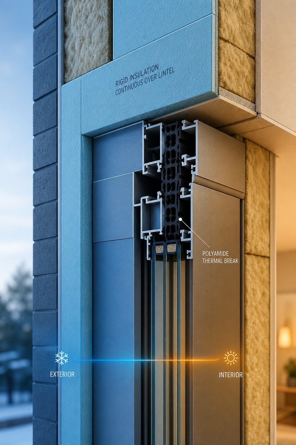
Polyamide thermal break strips within the aluminium extrusion are the first line of defence. These PA66 glass-fibre-reinforced bars, typically 14.8mm to 34mm wide, physically split the frame into separate interior and exterior sections connected only by the insulating strip. Will Enterprise’s technical data shows that a standard aluminium frame without a thermal break has a frame U-value (Uf) of approximately 5.0–7.0 W/m²·K. A 24mm thermal break reduces this to 1.8–2.5 W/m²·K — a dramatic reduction that keeps interior surface temperatures well above condensation thresholds under normal conditions.
But the frame alone isn’t enough. When you examine windows in section, the insulation layer in the surrounding wall must connect continuously through the head zone. Insulation needs to lap over the top of the lintel and bridge across to the cavity insulation on either side. If it stops short — leaving the lintel exposed within the cavity — heat bypasses the wall insulation entirely by travelling through the uninsulated lintel body. The Payette research team described this effect as “flank loss”: poor thermal performance in the area directly surrounding the window caused by structural elements interrupting the insulation plane.
The fix is methodical rather than complex. Rigid insulation board (PIR or phenolic) should be cut tightly around the lintel profile and mechanically fixed or adhesive-bonded to maintain position. Where proprietary cavity lintels incorporate EPS or PIR insulation within their profile, this step is handled by the product itself. For site-formed insulation closures, the critical check is simple: can you trace a continuous insulation line in your window detail section from the bulk wall insulation, over the lintel, and down to meet the frame’s thermal break? If there’s a gap anywhere in that line, heat will find it.
Thermal performance at the head is only as good as the weakest link in the insulation chain. A thermally broken aluminium profile loses its benefit entirely if the lintel above it conducts heat freely across the cavity, or if insulation stops 50mm short of the frame junction.
Condensation Risk and Mitigation
Thermal bridging at the head doesn’t just waste energy — it creates the surface conditions for condensation. When interior surface temperatures at the frame head drop below the dew point of the indoor air, moisture condenses directly on the aluminium profile or on the adjacent plasterboard reveal. In Australian coastal climates with high indoor humidity (kitchens, bathrooms, laundries), this can occur even when outdoor temperatures are relatively mild.
Testing data from thermal break manufacturers illustrates the scale of the problem. At -10°C exterior temperature with 21°C and 50% relative humidity inside, a non-thermally-broken aluminium frame’s interior surface drops to approximately 5°C — well below the 10°C dew point. A 24mm thermal break keeps that surface above 15°C, eliminating the condensation trigger. Australian conditions rarely reach those extremes, but even in Melbourne or Canberra winter nights at 2–5°C, a non-thermally-broken frame with an uninsulated lintel above it can produce interior surface temperatures low enough to trigger condensation at typical indoor humidity levels.
Beyond surface condensation, interstitial condensation presents a hidden risk within the head assembly itself. Warm, moist interior air migrating outward through gaps in the air seal reaches its dew point somewhere within the wall structure — often at the cold face of the lintel or behind the outer leaf. This moisture becomes trapped, unable to evaporate, gradually saturating insulation (which then loses its thermal properties), corroding metal fixings, and promoting mould growth in concealed locations.
Three measures mitigate condensation risk at the head:
- Warm-side air sealing — a continuous, vapour-resistant seal on the interior face of the frame-to-structure junction. This prevents moisture-laden indoor air from migrating into the cold cavity zone behind the frame. The vapour control layer must be on the warm side of the insulation, not the cold side.
- Ventilation in the cavity above — particularly in masonry cavity walls, the cavity must remain ventilated above the window head to allow any residual moisture to dry out. Blocking the cavity with debris, over-filled insulation, or mortar droppings traps moisture and accelerates degradation.
- Continuous insulation and thermal break specification — maintaining insulation continuity over the lintel and specifying thermally broken aluminium profiles keeps interior surface temperatures above dew point under normal operating conditions, removing the condensation trigger entirely.
The interplay between heat flow, moisture migration, and surface temperature at the head is precisely why this junction demands more design attention than it typically receives. A window detail section that shows only the physical components — without annotating the thermal and vapour control lines — misses half the story. And as anyone who has traced the source of mysterious damp patches on a ceiling near a window can confirm, the consequences of that oversight tend to appear two or three winters after construction, long after the builder has moved on.
Knowing what goes wrong thermally sets up the final practical question: in what order do you actually build this assembly on site, and which installation mistakes create these thermal and moisture failures in the first place?
Installation Sequencing and Avoiding Common Failures
Understanding each layer’s role is essential — but on a building site, knowledge alone doesn’t prevent defects. Sequence does. The aluminium window head detail is an assembly where every component depends on the one before it being correctly positioned, secured, and verified. Skip a step or install something out of order, and you lock a failure into the wall that’s invisible until water appears inside two winters later.
From the installer’s perspective, the head junction is also where time pressure collides with precision. Bricklayers, window installers, and waterproofers all converge at this point, often across different site visits. If the hand-off between trades isn’t clean, gaps open in the system — sometimes literally.
Step-by-Step Assembly Sequence
The correct window framing detail at the head follows a strict installation order. Each step creates the substrate or condition that the next step relies on:
- Lintel installation and bearing verification — Bed the lintel on full mortar beds with minimum 150mm bearing at each end. Check level along the length and across the width. An out-of-level lintel tilts the cavity tray and creates low points where water pools rather than drains. Verify that both inner and outer leaf bearings are solid before proceeding.
- Cavity tray and DPC positioning — Install the cavity tray directly above the lintel (or confirm it’s integral if using a proprietary lintel). The tray must rise at least 150mm up the inner face of the outer leaf. Fit sealed stop ends at both ends of the tray with returns folded back and lapped. Ensure the tray slopes slightly toward the outer leaf so moisture drains outward through weep provision.
- Insulation closure at the head — Cut rigid insulation (PIR or phenolic board) to fit tightly over the lintel and bridge to the bulk cavity insulation on either side. This step must happen before the frame goes in — once the frame is installed, accessing the head zone to add insulation becomes extremely difficult. A break in insulation continuity here creates the thermal bridge discussed in the previous section.
- Frame installation with head packers and clearance check — Position the aluminium frame in the opening. Insert non-compressible packers between the frame head and the lintel soffit at maximum 450mm centres, and within 150mm of each corner and each mullion. Sparwindows’ fitting guide recommends packers at 150mm from the top and bottom of the frame with a maximum 450mm between each. Check that head clearance is 5–10mm — enough for structural deflection and thermal expansion, but not so much that the sealant joint becomes excessively deep.
- Mechanical fixing — Secure the frame to the structure using fixings aligned with the packer positions. In masonry construction, use frame screws (typically 7.5 x 110–120mm) drilled through the frame into the inner blockwork or reveal. In timber frame, fix through the frame flanges or use galvanised installation straps at regular intervals. Fixing centres depend on frame size — windows above 1500mm wide require additional fixings at mid-span of the head.
- External weathering seal — With the frame mechanically restrained and confirmed plumb and level, apply the external seal. Insert a closed-cell polyethylene backer rod to control sealant depth (width-to-depth ratio of 2:1), then gun neutral-cure silicone sealant into the joint. The substrate must be clean, dry, and free of dust or mortar residue. Any contamination on the bonding surfaces causes adhesion failure within months.
- Internal air seal — Apply the warm-side seal at the interior frame-to-structure junction. This can be a continuous bead of appropriate sealant, a preformed compriband expanding foam tape, or a self-adhesive airtight membrane. Its purpose is to prevent moist indoor air from migrating into the cold cavity zone behind the frame head — the primary defence against interstitial condensation.
Each step in this detail window section sequence depends on the preceding one. The cavity tray can’t be correctly positioned without a level lintel. The insulation closure can’t bridge properly if the tray isn’t already in place to form one boundary. The frame can’t be packed accurately without the insulation and tray established above. And the sealants — both external and internal — can’t be applied until the frame is mechanically fixed and stationary.
Critical Tolerances and On-Site Checks
Tolerances at the head are tight, and site conditions rarely match drawing-board precision. The following checks should happen before any sealant is applied — because sealant hides problems rather than solving them:
- Head clearance: Measure the gap between the frame head and lintel soffit at three points — both ends and centre. The gap should be 5–10mm uniformly. Less than 5mm risks frame distortion under lintel deflection or thermal expansion. More than 12–15mm creates an excessively deep sealant joint that may slump or fail to cure through its full depth.
- Packer spacing: Maximum 450mm between packers. Packers must sit within 150mm of each corner and directly beneath each mullion. They should be non-compressible material (hardwood shims or proprietary plastic packers), not soft timber offcuts that compress over time and transfer load unevenly.
- Plumb and level: Check the frame with a spirit level on both jambs and across the head before fixing. Open and close the sash — a frame that’s racked even slightly will cause hardware binding and uneven gasket compression that reduces weather performance. Standard fitting practice confirms that opening and closing the window after packing but before final fixing is essential to verify correct operation.
- Fixing alignment: Fixings should pass through the frame at packer locations so that the clamping force is transmitted into the packer, not into an unsupported span of aluminium that can deflect inward. Misaligned fixings — drilled between packers — pull the frame out of plane and distort gasket seals.
- Cavity tray continuity: Before brickwork closes over the tray, visually verify that stop ends are sealed, the tray isn’t punctured by scaffold ties or other fixings, and weep holes align above (not below) the tray. Once the outer leaf is laid past this point, remediation requires demolition.
Common Failure Modes and How to Prevent Them
Site defects at the head are overwhelmingly installation errors rather than material failures. The same handful of mistakes appear repeatedly in defect reports, building inspections, and warranty claims on Australian residential projects. Each one is preventable — if you know what to look for.
A window detail brick wall installation in cavity masonry is particularly vulnerable because so many trades interact at the head zone. The following table documents the most common defects, what happens when they’re left uncorrected, and how to prevent them:
| Failure Mode | Consequence | Prevention Measure |
|---|---|---|
| Reversed cavity tray (outer edge higher than inner edge, or rear face turned forward) | Water collected by the tray drains inward toward the inner leaf instead of outward through weep holes. Damp patches appear on internal walls above the window within 6–12 months. | Mark the tray’s outer face clearly before installation. Verify the slope falls toward the outer leaf before laying the next course. Cavity tray guidance confirms the tray must slope slightly toward the outside so water flows out through weep holes. |
| Missing or unsealed stop ends | Water runs off the ends of the tray and drops into the cavity beside the window frame, saturating insulation and tracking into internal finishes at the frame corners. | Install preformed stop ends or fold the tray material back on itself at each end, sealing the fold with compatible mastic. Verify stop ends are in place before closing the cavity with further brickwork. |
| Insufficient head clearance (less than 5mm) | Structural deflection of the lintel under load or thermal expansion of the frame transmits compressive force into the frame head. This distorts the profile, breaks gasket seals, and causes hardware binding. In severe cases, the glass unit cracks. | Use calibrated packers — not offcuts — measured to achieve 5–10mm minimum clearance. Verify at three points before fixing. Never pack the head tight against the lintel in an attempt to “secure” the frame. |
| Sealant applied to dusty, wet, or contaminated surfaces | Adhesion failure within months. The sealant peels cleanly from the substrate, opening a direct path for water and air. Often not visible externally until the seal has fully debonded. | Clean bonding surfaces with isopropyl alcohol or manufacturer-recommended primer. Apply sealant only to dry substrates. If rain interrupts the process, allow surfaces to dry completely before sealing — never seal over damp masonry or wet aluminium. |
| Broken insulation continuity at the head | A thermal bridge forms above the window, dropping interior surface temperatures and causing localised condensation on the frame head or adjacent plasterboard. Over time, mould growth and lining damage follow. | Install rigid insulation over the lintel before the frame goes in. Ensure it laps to meet the cavity insulation on both sides without gaps. Check that no services, fixings, or scaffold ties have punctured or displaced the insulation after installation. |
| Blocked weep holes (mortar droppings or debris) | Water collected by the cavity tray cannot drain outward. The tray fills, overflows, and saturates the inner leaf and insulation. Damp appears at the head or gradually worsens with each rain event. | Place a cavity drainage mat or mortar catch mesh at the base of the cavity above the tray during bricklaying. Inspect weep holes before scaffold removal — a thin wire should pass through freely. TradeFox’s cavity tray guide identifies mortar blockage as the most common drainage failure in cavity walls. |
| Missing internal air seal | Warm, humid interior air migrates through the frame-to-structure gap into the cold cavity zone. Interstitial condensation forms on the cold face of the lintel or behind the outer leaf. Hidden moisture damages insulation, corrodes fixings, and promotes concealed mould growth. | Apply a continuous air seal on the warm (interior) side of the junction before internal linings are fitted. Use compatible sealant, compriband tape, or self-adhesive membrane. This seal must be continuous — any gap provides a path for vapour migration. |
The pattern across all these failures is consistent: each one is caused by something being missed, reversed, or contaminated during a brief window of access. Once the next trade covers the work — bricklayer closing the cavity, plasterer lining the reveal, painter finishing the internal trim — the defect is buried. It only reveals itself months or years later, when moisture damage becomes visible on finished surfaces and remediation costs multiply.
Preventing these defects isn’t about slowing the build down. It’s about sequencing the work so each trade leaves a verified, inspectable substrate for the next. A five-minute check at each stage — level lintel, sloped tray with stop ends, continuous insulation, correct clearance, clean substrate for sealant — eliminates the most common causes of head junction failure before they’re locked into the wall permanently.
With the assembly built and verified, the remaining question shifts from how to build it to how to choose the right approach for your specific project. That decision depends on your wall type, your performance targets, and how much specification support you can access from your window system supplier.

Selecting the Right Window Wall Section Detail for Your Project
Every project is different — and the head detail that works flawlessly on a double-storey brick veneer home in suburban Melbourne may fail spectacularly on a coastal weatherboard renovation in Port Macquarie or a three-storey mixed-use build in Brisbane. Choosing the correct approach isn’t about memorising a single “best practice” detail. It’s about matching the wall section with window configuration to your specific construction type, performance requirements, climate exposure, and design intent.
Three professional perspectives converge at this junction. The architect defines the aesthetic — recessed, flush, or projecting head. The engineer specifies the structural support and thermal performance targets. The installer determines how the assembly actually goes together on site, in what order, and within what tolerances. When all three perspectives align on a single, clearly documented head detail, the result is a junction that performs for decades. When they don’t, someone ends up improvising on a scaffold — and improvisation at the head is where leaks begin.
Decision Framework for Your Project
Rather than working backward from a generic detail and hoping it fits, follow a structured decision path that narrows your options at each stage. The sequence matters — each choice constrains the ones that follow:
Step 1: Identify your wall construction type. Masonry cavity, timber frame with cladding, steel frame, or rainscreen — each one dictates a fundamentally different interface at the head, as covered in the wall-type comparison earlier in this article. If you’re working with a hybrid system (say, brick veneer over timber frame), identify which element forms the structural opening and which forms the external skin. The structural element determines lintel type; the external skin determines flashing strategy.
Step 2: Select the appropriate lintel. Your wall type narrows the lintel options. Masonry cavity walls typically use pressed steel cavity lintels or precast concrete. Timber frames rely on engineered timber headers. Steel-framed buildings use steel headers within the structural wall. Proprietary cavity lintels with integrated DPC trays simplify the weathering layer by combining structure and drainage in one product — a significant advantage where site supervision is limited.
Step 3: Determine your head configuration. Recessed, flush, or projecting — each creates a different aesthetic and a different flashing geometry. A recessed head suits deep lintels and creates shadow lines. A flush head aligns the frame with the outer wall face for a clean, modern window house appearance. A projecting head sheds water forward with a drip detail but requires additional mechanical fixing above the frame.
Step 4: Specify the flashing approach. Cavity tray with stop ends and weep holes for masonry. Membrane and metal head flashing lapped under sarking for timber frame. Projecting head flashing extending past the cladding face for rainscreen. The flashing type follows directly from the wall type and head configuration — it’s not an independent decision.
Step 5: Choose the sealant system. Neutral-cure silicone for exposed aluminium-to-masonry junctions. Polyurethane for concealed joints behind trim. Compriband or expanding foam tape for the internal air seal. Match the sealant to the substrate, the joint width, and the expected movement.
Before finalising any window wall section detail, practitioners should work through these key questions:
- What is the wall build-up, and where does the aluminium frame sit relative to the outer face — inboard, flush, or outboard?
- What lintel type does the structural design specify, and what is its profile depth?
- Is the cavity tray integral to the lintel or does it need to be site-formed?
- What is the minimum head clearance achievable given lintel depth and course heights?
- Does the project require thermally broken aluminium profiles to meet NCC energy efficiency requirements?
- What is the site’s wind classification, and does the head sealant joint need to resist specific water penetration pressures under AS 2047?
- Is the building in a coastal salt zone, cyclone region, or bushfire-prone area requiring specific material or fixing upgrades?
- Who is responsible for each layer — bricklayer, window installer, waterproofer — and is the installation sequence documented?
Answering these questions before any materials are ordered or any opening is formed eliminates the most common cause of head detail failure: ad hoc decision-making on site when the correct information isn’t available.
Standards and Compliance Checklist
In Australia, the aluminium window head detail doesn’t exist in regulatory isolation. It’s part of a broader compliance framework that governs window performance, weather resistance, and energy efficiency at every junction — head, sill, and jamb alike.
AS 2047 is the primary Australian Standard for windows and external glazed doors. It mandates testing for structural performance under wind load, water penetration resistance, and air infiltration — all of which are directly affected by how the head junction is detailed and sealed. A window system that passes AS 2047 testing in the laboratory can still fail in the field if the head detail doesn’t maintain the same seal integrity achieved under controlled conditions. The standard’s water penetration test applies pressure to the full window assembly, including the frame-to-structure junction — meaning sealant quality, joint geometry, and flashing integrity at the head are all implicit in the test result.
AS 4420 provides the testing methods referenced by AS 2047, specifying exactly how air infiltration, water penetration, and structural adequacy are measured. For practitioners, the relevant takeaway is that these tests simulate real wind-driven rain pressures, not just static water exposure. A head detail that holds water out under gravity alone but fails under pressure differential is non-compliant — and this is precisely the condition that occurs during Australian storms when wind-driven rain pushes moisture upward behind flashings and into gaps that appear weathertight in calm conditions.
The National Construction Code (NCC) references both AS 2047 and energy efficiency requirements, tying window performance directly to building approval. NCC Volume 2 (for residential Class 1 and 10 buildings) requires windows to meet weatherproofing and energy efficiency benchmarks appropriate to the building’s climate zone. Thermally broken aluminium frames, correct insulation continuity at the head, and appropriate glazing specifications all contribute to meeting NatHERS (Nationwide House Energy Rating Scheme) targets — which directly influence whether a project achieves the minimum 7-star energy rating required for new residential builds.
For projects in specific exposure zones, additional requirements layer on top:
- Cyclone regions (northern Queensland, NT, parts of WA) — higher wind classifications demand stronger fixings, heavier lintel sections, and sealant joints rated for greater pressure differentials at the head.
- Bushfire-prone areas — BAL (Bushfire Attack Level) ratings may require specific glazing types, ember-guard mesh, and non-combustible framing materials at the window junction. Head details in BAL-29 or BAL-40 zones must prevent ember entry through gaps at the frame-to-structure interface.
- Coastal salt zones — aluminium frames and fixings must be rated for marine environments. Stainless steel fixings, marine-grade powder coating, and sealants resistant to salt degradation become mandatory rather than optional at the head junction.
Compliance isn’t a separate exercise you perform after the detail is designed. It’s the framework within which every decision — lintel type, flashing material, sealant chemistry, insulation specification — should be made from the outset.
Where to Find Specification Support
Generic details from textbooks and online guides provide a solid foundation, but every project eventually reaches a point where the generic stops being enough. Specific frame profiles have specific fixing requirements. Particular lintel-to-frame combinations create unique clearance geometries. Climate zone requirements, BAL ratings, and wind classifications add performance layers that a one-size-fits-all drawing can’t address.
This is where working with your window system manufacturer becomes genuinely valuable — not as a sales exercise, but as a technical collaboration. Reputable manufacturers maintain libraries of tested, project-specific details for their aluminium profiles. These details are drawn to match the actual extrusion dimensions, thermal break widths, and fixing lug positions of the products being supplied. They eliminate the guesswork that occurs when an architect draws a generic aluminium frame section on a wall section with window detail and hopes it aligns with what arrives on site.
For Australian residential and commercial projects, MEICHEN’s aluminium window systems offer custom options and project-ready integration across common Australian construction types — from brick veneer and timber frame through to commercial applications. Their product page provides window type options and specification pathways relevant to practitioners finalising head detail designs, whether you’re planning a new build in a coastal zone or a renovation on an existing brick veneer home. Having access to manufacturer-specific section details that match the actual product being installed closes the gap between design intent and site reality.
Regardless of which supplier you work with, request the following from your window manufacturer before finalising any head detail:
- Dimensioned cross-section drawings of the head profile, including thermal break position and fixing lug locations
- Recommended head clearance for the specific frame series
- Compatible sealant types and joint geometry recommendations
- Fixing schedule — type, size, and maximum centres for the frame series and opening size
- AS 2047 test report confirming the window system’s water penetration resistance rating
- Installation guide specific to the frame series, including packing and sealing procedures
A head detail that’s been coordinated between the architect’s design intent, the engineer’s structural and thermal requirements, and the manufacturer’s tested installation methodology has the strongest chance of performing as intended. The alternative — a detail pieced together from assumptions, generic references, and site improvisation — is exactly how water finds its way in.
Frequently Asked Questions About Aluminium Window Head Details
1. What is a window head detail and why does it matter?
A window head detail is the horizontal junction at the top of a window frame where the aluminium profile meets the wall structure above. It includes the lintel, cavity tray or flashing, insulation closure, sealant lines, and the frame head profile itself. This junction matters because gravity drives water directly onto it from the wall above, making it the most common origin point for window leaks. When any component in this integrated weathering system fails or is poorly coordinated, moisture penetrates the building envelope, leading to water damage, thermal bridging, condensation, mould growth, and premature structural deterioration.
2. How much head clearance should be left above an aluminium window frame?
Standard practice requires a minimum head clearance of 5 to 10mm between the top of the aluminium frame and the underside of the lintel soffit. This gap accommodates structural deflection of the lintel under load, thermal expansion of the frame, and normal construction tolerances. Non-compressible packers at maximum 450mm centres maintain this gap uniformly. Less than 5mm risks frame distortion and gasket seal failure, while more than 12 to 15mm creates an excessively deep sealant joint that may slump or fail to cure properly. The gap receives a closed-cell polyethylene backer rod and neutral-cure silicone sealant to form the weather seal.
3. What type of sealant should be used on aluminium window head junctions?
Neutral-cure silicone sealant is the preferred choice for aluminium window head junctions. Unlike acetoxy (vinegar-cure) silicones, neutral-cure formulations do not emit acetic acid during curing, which can corrode aluminium, anodised finishes, and galvanised steel flashings. They bond reliably to clean aluminium, powder-coated surfaces, glass, and most masonry substrates. Polyurethane sealants are suitable for concealed joints behind trim due to their higher abrasion resistance and paintability, but they offer less UV stability for exposed applications. Joint geometry should maintain a 2:1 width-to-depth ratio controlled by a backer rod to prevent three-sided adhesion and premature cohesive failure.
4. How do you prevent thermal bridging at an aluminium window head?
Preventing thermal bridging at the window head requires three coordinated measures. First, specify thermally broken aluminium profiles with polyamide strips (typically 14.8mm to 34mm wide) that split the frame into separate interior and exterior sections, reducing frame U-values from approximately 5.0 to 7.0 W/m2K down to 1.8 to 2.5 W/m2K. Second, maintain insulation continuity by installing rigid insulation board (PIR or phenolic) over the lintel, bridging to the bulk cavity insulation on both sides without gaps. Third, apply a warm-side air seal at the interior frame-to-structure junction to prevent moist indoor air migrating into the cold cavity zone, which causes interstitial condensation and hidden moisture damage.
5. What are the most common installation mistakes at the aluminium window head?
The most frequently documented defects at the aluminium window head include reversed cavity trays that drain water inward instead of outward, missing or unsealed stop ends that allow water to run off tray edges into the cavity, insufficient head clearance causing frame distortion under lintel deflection, sealant applied to dusty or wet surfaces resulting in adhesion failure, broken insulation continuity creating thermal bridges and condensation, blocked weep holes from mortar droppings during bricklaying, and missing internal air seals that permit warm humid air to reach cold zones. Each defect is caused by something being missed or reversed during a brief window of access, then buried by subsequent trades.
More Window & Door Guides