What Is an Aluminium Window Frame Cross Section
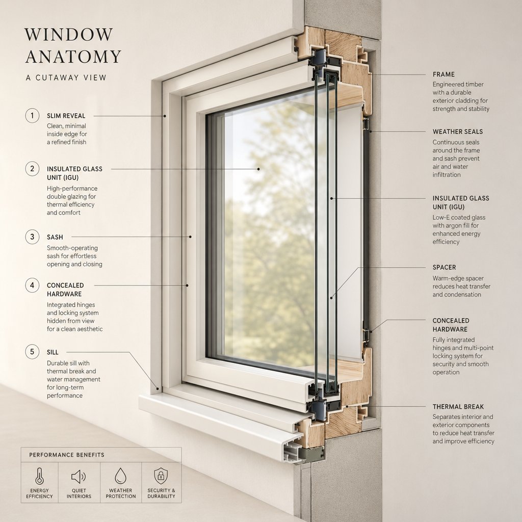
Every aluminium window profile hides a surprising level of engineering beneath its sleek exterior surface. The only way to see that complexity is to slice through the frame and look at what is inside. That slice is the cross section, and it is arguably the single most important drawing in any window specification package.
An aluminium window frame cross section is a two-dimensional view created by cutting through a profile perpendicular to its length, revealing internal chambers, wall thicknesses, thermal break cavities, gasket channels, and drainage paths that collectively determine the window’s structural, thermal, and weatherproofing performance.
Whether you are an architect drafting a window section detail for council submission, a builder checking compatibility with a brick veneer reveal, or a homeowner trying to compare quotes, understanding this drawing gives you a shared technical language with your supplier.
What a Cross Section Actually Shows
Imagine taking a hacksaw to an aluminium window frame at a right angle and examining the freshly exposed face. That is the conceptual cut a cross section represents. Instead of seeing a solid block of metal, you would find a complex arrangement of hollow chambers separated by thin aluminium walls. You would also see grooves machined for rubber gaskets, slots designed for drainage, recesses that accept glazing beads, and, in thermally broken profiles, a distinct gap bridged by polyamide strips separating the exterior and interior aluminium faces.
A window frame diagram drawn from this perspective communicates more about performance than any external photograph ever could. It reveals how thick the aluminium walls are, how many air chambers provide insulation, where water escapes, and how hardware attaches.
Why Cross Sections Matter for Window Selection
A single window frame detail drawing encodes four critical performance stories at once. First, structural capacity: the depth of the profile and number of internal webs determine how much wind load the frame can resist. Second, thermal performance: the presence and width of thermal break cavities directly influence U-values. Third, drainage design: strategically placed slots and pressure-equalised chambers prevent water ingress during driven rain. Fourth, hardware compatibility: screw bosses and reinforcement pockets dictate which locks, hinges, and stays the profile can support.
For Australian projects assessed against NCC energy requirements and AS 2047 performance standards, these four factors combine to determine whether a window system will pass certification. Reading the cross section with confidence is the first step toward making that assessment yourself, rather than relying solely on a supplier’s claims.
The vocabulary used within these drawings, however, can be dense. Terms like web, flange, screw boss, and glazing rebate appear without explanation in most technical catalogues, which is exactly why a clear glossary of cross-section terminology becomes essential.
Essential Cross-Section Terminology Explained
Open any technical catalogue for aluminium window profiles and you will encounter a dense layer of jargon. Without a shared vocabulary, even a well-drawn window detail section becomes difficult to interpret. The table below defines the key elements you will meet when examining a profile drawing, organised by where each feature sits and what it does.
| Term | Location in Profile | Function |
|---|---|---|
| Web | Internal vertical or diagonal wall connecting outer and inner faces | Provides structural rigidity and divides the profile into discrete chambers |
| Flange | Projecting lip along the outer or inner perimeter edge | Creates a fixing or overlap surface for adjacent components such as glazing beads or sub-frames |
| Chamber | Enclosed hollow space between webs | Adds stiffness without extra weight; can trap still air for insulation |
| Tongue and groove | Interlocking projections and recesses where two profiles meet | Aligns and locks mating parts together, reducing reliance on mechanical fasteners |
| Thermal break slot | Gap between exterior and interior aluminium faces | Houses the polyamide bar that interrupts heat flow across the profile |
| Gasket channel | Recessed groove on interior or exterior face edges | Retains rubber or EPDM seals under compression to block air and water |
| Drainage slot | Small opening at the lowest point of a chamber or rebate | Allows condensation or wind-driven moisture to escape to the exterior |
| Screw boss | Thickened internal pocket, usually adjacent to a chamber wall | Provides solid material for self-tapping screws that attach hardware or accessories |
| Glazing rebate | Stepped recess along the sash or frame face | Receives the glass unit and glazing bead, securing the pane in position |
Structural Elements of the Profile
Webs, flanges, and chambers form the skeleton of every window profile. Webs act as internal bracing walls, and a profile’s rib-like web pattern largely dictates its moment of inertia, the measure of how well it resists bending under wind pressure. Flanges extend outward from that skeleton, providing overlap surfaces for weatherseals, fixing lugs, or snap-fit glazing beads. Chambers, the hollow voids created between webs, serve a dual purpose: they reduce material weight and, when sealed, create pockets of still air that slow heat transfer. More chambers generally mean a stiffer, better-insulating section, though each additional web must remain extrudable within the alloy’s minimum wall thickness limits.
Sealing and Performance Features
Where structural elements give a window profile its strength, sealing features give it weathertightness. Gasket channels are precision-formed grooves that grip rubber or EPDM seals tightly enough to maintain compression over decades of thermal cycling. Their geometry must match the gasket’s cross-sectional shape exactly, so these channels are among the tightest-tolerance zones in the entire extrusion.
The thermal break slot is perhaps the most performance-critical cavity in a modern profile. It appears as a clearly defined gap, typically 20 mm to 40 mm wide in thermally broken window profiles sold in Australia, bridged only by reinforced polyamide strips that prevent direct metal-to-metal heat conduction between inside and outside.
Drainage slots complete the picture. Positioned at strategic low points, they form a controlled exit path for any moisture that breaches the outer seal. In pressure-equalised designs, these slots also balance air pressure between chambers so that wind cannot force water inward. Recognising these features on a drawing is the difference between reading a window detail section passively and genuinely evaluating whether a profile will perform in your climate zone.
With this vocabulary in hand, the next logical question becomes how these elements change shape depending on whether the profile serves as a frame, sash, mullion, or transom, each structural role placing different geometric demands on the same set of components.

How Cross-Section Geometry Varies by Profile Role
Not every aluminium window profile in a completed window unit looks the same in cross section. Each component carries different loads, interfaces with different materials, and serves a different purpose within the overall assembly. The geometry of a profile, its depth, wall thickness, chamber layout, and reinforcement zones, shifts to match that specific structural role. Four distinct roles define most window systems: frame, sash, mullion, and transom.
Frame and Sash Profile Geometry
The frame profile is the perimeter member fixed directly into the wall opening. It anchors the entire window to the building structure, so its cross section tends to be the widest and most anchor-point-rich of any component. You will typically see deeper sections with multiple screw boss pockets along the fixing face, giving installers solid material for masonry anchors or timber screws at regular centres. The outer flange often includes a fin or lip designed to overlap the reveal, creating a primary weather barrier at the frame-to-wall junction. For Australian brick veneer construction, this fixing flange geometry determines whether the frame can sit flush with the brickwork or requires a separate sub-frame adaptor.
The sash profile, by contrast, carries the glass and either operates on hardware or sits fixed within the frame. Its cross section is lighter and shallower. Depth is kept to a minimum so that sightlines stay slim and the operable weight remains manageable for friction stays or hinges. Instead of multiple screw bosses for structural fixings, the sash features hardware channels, precision-machined grooves or pockets that accept espagnolette locks, cam handles, and stay brackets. A deeper glazing rebate accommodates the insulated glass unit, while dual gasket channels on opposite faces create the inner and outer seal lines.
An architect reading these two profiles side by side judges sightline proportions and thermal break continuity. A fabricator, however, focuses on whether the screw boss spacing in the frame matches their preferred anchor pattern and whether the sash hardware channel accepts the specified lock without secondary machining.
Mullion and Transom Cross Sections
Mullions divide a window opening vertically. Transoms do the same job horizontally. Both carry wind loads across spans that can exceed two metres in residential openings and far more in commercial facades. Their cross sections reflect that structural demand through noticeably deeper profiles and a higher chamber count compared to standard frame or sash sections.
A mullion’s aluminium window frame profile is typically symmetrical about its vertical axis, because it receives equal glazing loads from both sides. That symmetry translates into mirrored glazing rebates, twin gasket channels, and a central web cluster that maximises the moment of inertia, the property that resists bending. Transoms share a similar logic but are oriented horizontally, meaning they also manage gravity loads from the glass above. Their lower flange is often thicker or reinforced to handle that sustained dead weight without creeping over time.
In larger openings subject to high wind regions under AS 2047 testing, mullions and transoms may incorporate steel or aluminium reinforcement bars slotted into dedicated internal chambers. These reinforcement pockets appear in the cross section as oversized rectangular voids, clearly distinct from the smaller insulation chambers surrounding them.
- Frame: Widest section, multiple screw bosses for structural fixing, fixing fin for wall overlap, deeper thermal break zone
- Sash: Shallower depth for slim sightlines, hardware channels for locks and stays, dual gasket tracks, generous glazing rebate
- Mullion: Symmetrical profile, mirrored glazing rebates, high moment of inertia from central web cluster, reinforcement bar pocket for high-wind spans
- Transom: Similar depth to mullion but with a thicker lower flange to support dead loads, horizontal drainage paths, and capacity for structural reinforcement
For specifiers, these geometric differences determine whether a system can span a given opening without visible deflection. For installers and fabricators, they dictate cutting sequences, reinforcement insertion steps, and the order of gasket threading during assembly. Both perspectives converge on the same principle: the cross-section shape is never arbitrary. It is a direct expression of the forces and functions each profile must handle.
What determines how thin those walls can be or how complex the chamber layout becomes? That question leads directly to the aluminium alloy itself, where extrudability limits and strength grades set the physical boundaries of every profile geometry.
How Alloy Selection Shapes Cross-Section Design
The aluminium alloy chosen for a window profile is not a background detail buried in a material certificate. It directly governs how thin walls can be extruded, how complex the chamber layout can become, and how much structural load the finished section will carry. Three alloys dominate the aluminium window frame material landscape: 6063, 6060, and 6061. Each belongs to the 6xxx series (magnesium and silicon as primary alloying elements), yet their behaviour during extrusion and their finished mechanical properties differ enough to produce distinctly different cross-section geometries.
Alloy Properties That Constrain Profile Design
Extrudability is the critical factor. It describes how readily molten billet flows through a die to form the intricate hollow shapes that window profiles demand. Alloy 6063 is the industry benchmark, rated as the easiest to extrude among structural aluminium grades. Its low flow stress allows the metal to fill thin webs, tight gasket channels, and complex multi-chamber hollows without tearing or surface cracking. According to extrudability research, all other alloys are compared against 6063 with an index of 100, and increasing numbers indicate greater difficulty.
Alloy 6060 behaves similarly, with marginally lower magnesium content that makes it slightly easier to push through intricate dies. Both 6060 and 6063 in T5 or T6 temper deliver the smooth surface finish and fine detail needed for an aluminium profile for windows where appearance matters as much as performance.
Alloy 6061-T6 sits at the other end of the trade-off. It offers significantly higher yield strength, around 241 MPa compared to 159 MPa for 6063-T6, making it suitable where structural demand is extreme. The cost is reduced extrudability. Thinner walls become harder to achieve cleanly, and complex hollow chambers risk incomplete fill or surface tearing. For most residential and commercial aluminium window profiles, 6063-T5 provides more than adequate strength while allowing the thin-walled, multi-chamber geometries that deliver thermal and structural efficiency. Alloy 6061 tends to appear only in specialised structural mullions or high-load curtain wall components where simpler, heavier sections are acceptable.
Wall Thickness Standards and Tolerances
Wall thickness is where alloy capability meets regulatory requirement. In Australia, aluminium profiles for windows and doors must comply with AS/NZS 1866, which covers extruded rod, bar, and hollow shapes for construction. Minimum measured wall thickness for window profiles is 1.4 mm, while door profiles require at least 2.0 mm. These figures represent the thinnest point after extrusion tolerances are applied, not the nominal dimension on the drawing.
Dimensional precision during extrusion varies by alloy group. European standard EN 755-9, which informs much of the tolerance logic used in Australian specifications, classifies 6060 and 6063 as Group I alloys, meaning they achieve tighter dimensional tolerances than harder alloys in Group II. For a window fabricator, this means a 6063 profile will arrive closer to its nominal wall thickness, with less variation across a production run. That consistency matters for gasket fit, hardware engagement, and thermal break crimping, where even fractions of a millimetre affect seal compression and long-term weathertightness.
In practice, most aluminium sliding windows material and casement window profiles are extruded from 6063-T5 with wall thicknesses between 1.4 mm and 2.0 mm for standard residential systems. Commercial systems push that range to 2.5 mm or even 3.0 mm in deep mullion sections, still using 6063 but with greater cross-sectional depth rather than a jump to a harder alloy. The result is a profile that remains economical to extrude while meeting the structural demands of larger spans.
This interplay between alloy grade, wall thickness, and chamber complexity sets the physical envelope of every cross section. But geometry and material are only part of the performance equation. Inside many of these profiles sits a deliberate gap, a thermal break cavity, whose width and internal detailing transform a simple aluminium extrusion into a genuine insulating system.
Thermal Break Design Inside the Profile
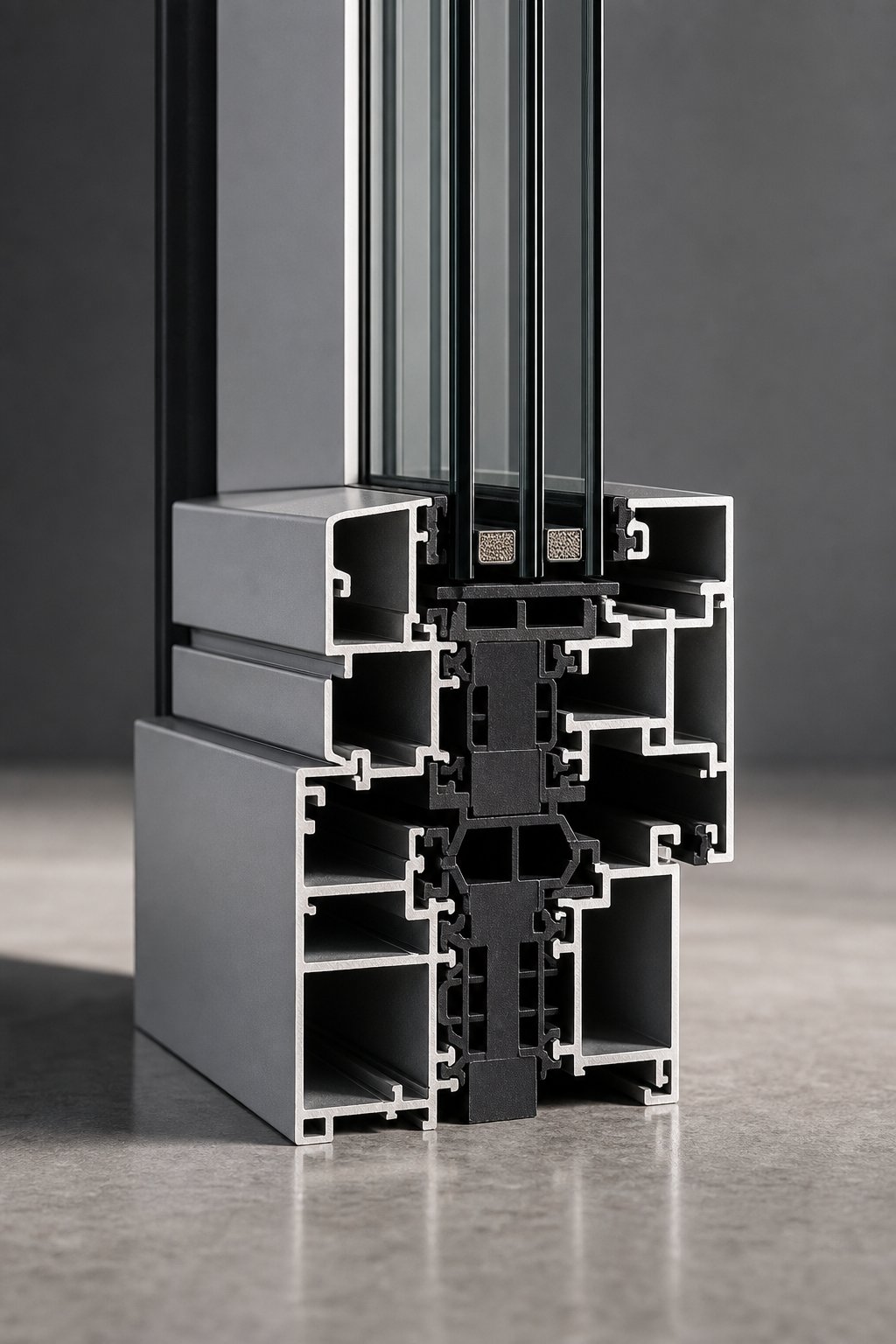
Strip away the external powder coat and look at an aluminium window frame cross section through thermally broken aluminium window frame extrusions, and one feature dominates the drawing: a clearly defined gap separating the exterior aluminium face from the interior aluminium face. That gap is not empty space waiting to be filled. It is the thermal break zone, and the material bridging it is the single biggest contributor to the profile’s insulation performance.
The barrier itself is a strip of PA66 (Polyamide 66) reinforced with 25% glass fibre, commonly abbreviated as PA66 GF25. This engineered plastic has a thermal conductivity of roughly 0.30 W/(m·K), compared to aluminium’s 160 W/(m·K). In practical terms, the polyamide conducts heat about 500 times more slowly than the metal surrounding it. By replacing a continuous aluminium path with this low-conductivity strip, the profile’s ability to transfer heat from one face to the other drops dramatically.
Identifying the Thermal Break in a Cross Section
On a technical drawing, the thermal break appears as a distinct zone, usually hatched or shaded differently from the aluminium sections flanking it. Two aluminium halves sit either side of the gap, connected only by the polyamide bars. Look closely at the connection points and you will see a crimped or knurled interface where the aluminium has been mechanically deformed around the strip’s edges. This crimping locks the polyamide in place without adhesive, relying on friction and mechanical interlock to maintain the bond across decades of thermal cycling.
Surrounding the bars, you will often spot small enclosed air pockets within the break zone itself. These are not manufacturing defects. They are deliberately shaped cavities that add another layer of insulation by trapping still air, which conducts heat poorly. In older single-chamber designs, you might see just one polyamide strip with minimal surrounding void. Modern multi-chamber window aluminum profile systems use two or more parallel bars with sculpted air chambers between them, stacking insulation layers within the same overall break width.
How Cavity Width Affects Thermal Performance
The width of the thermal break cavity is one of the simplest predictors of frame insulation quality. Early thermally broken aluminium window frame extrusions featured cavities as narrow as 14 mm. Current high-performance systems push that dimension to 35 mm or more, with some passive-house-grade profiles reaching 44 mm. Each additional millimetre of separation between the hot and cold aluminium faces lengthens the path heat must travel, reducing the frame’s U-value.
To put numbers around it: a basic thermal break system might deliver a frame U-value of 2.0 to 2.5 W/(m²·K), while a premium multi-chamber design achieves 0.8 to 1.2 W/(m²·K). That range spans the difference between a profile that barely satisfies NCC Section J energy provisions and one that comfortably exceeds them, even in cooler southern climates like Hobart or the alpine regions of Victoria.
It is worth noting that cavity width alone does not tell the whole story. The number of air chambers within the break zone, the geometry of those chambers, and the stiffness of the polyamide bars all interact. A 24 mm cavity with three internal air chambers can outperform a 30 mm cavity with a single open void, because subdivided chambers suppress convective air movement more effectively.
Surface treatments also play into dimensional precision at this scale. Anodising adds between 5 and 25 microns per face, while powder coating deposits a film 60 to 120 microns thick. On a cross-section specification drawing, these coatings appear as measurable additions to the profile’s outer dimensions. For the thermal break connection, coating thickness on the crimping faces must be controlled tightly. Too much build-up in the knurl zone can reduce the mechanical grip between aluminium and polyamide, compromising long-term integrity. Fabricators working with precision window aluminum profile assemblies account for this by specifying coating exclusion zones at crimp locations or adjusting crimp pressure to compensate.
Taken together, alloy selection, wall thickness, and thermal break geometry define what a profile can achieve in isolation. But the performance demands placed on that profile shift considerably depending on whether it sits in a double-storey home in suburban Melbourne or a fifteen-storey commercial tower on the Gold Coast waterfront, a distinction that reshapes cross-section requirements from the ground up.

Residential vs Commercial Cross-Section Requirements
A 50 mm deep aluminium windows profile that performs beautifully in a single-storey suburban home would be structurally inadequate on the tenth floor of a coastal office tower. The forces, glass sizes, and lifecycle expectations are fundamentally different, and those differences write themselves directly into cross-section geometry. Understanding where residential and commercial window profiles aluminium diverge helps specifiers avoid under-engineering a facade or over-spending on a house.
Residential Profile Characteristics
Residential systems prioritise slim sightlines and visual proportion. Homeowners want maximum glass area and minimal frame intrusion, so profile depths stay shallow, typically between 44 mm and 72 mm for frames and even less for operable sashes. Wall thicknesses sit at the lower end of the permissible range, commonly 1.4 mm to 1.8 mm, keeping material cost and weight down without sacrificing compliance with AS 2047.
Chamber count in residential profiles is moderate, usually two to four chambers per section. That is enough to provide reasonable thermal insulation and structural stiffness across typical residential spans of 600 mm to 1200 mm between support points. Thermal break widths range from 20 mm to 34 mm, sufficient to achieve frame U-values that satisfy NCC Section J for most Australian climate zones. Glazing rebates accommodate standard double-glazed units of 20 mm to 24 mm total thickness.
Cost efficiency drives much of the design logic. Residential profiles use simpler die geometries that are cheaper to manufacture and replace, and the lighter sections require less aluminium per linear metre, reducing raw material expense across a full-house window package.
Commercial and Curtain Wall Profile Differences
Commercial aluminium window details tell a different story. Profile depths jump to 100 mm, 150 mm, or beyond for mullions spanning floor-to-floor heights of 3000 mm or more. At these spans, wind suction pressures, particularly at building corners and upper floors, demand a far higher moment of inertia than any residential section can deliver. As outlined in structural curtainwall design fundamentals, mullions must limit deflection to L/175 for spans under approximately 4100 mm, a criterion that forces deeper, heavier profiles with thick internal web clusters.
Wall thicknesses in commercial systems typically range from 2.0 mm to 3.0 mm, and chamber counts reach six or more. Those extra chambers serve structural and drainage functions simultaneously. Pressure-equalised rainscreen cavities, a hallmark of commercial facade design, rely on carefully sequenced chambers that balance air pressure between exterior and interior environments, preventing wind-driven rain from migrating inward. These drainage chambers appear in cross-section drawings as distinct voids with dedicated slots open to the exterior.
Glazing capacity also scales up. Commercial profiles accommodate insulated glass units 28 mm to 50 mm thick, including laminated inner and outer panes for safety compliance at height. Structural silicone glazing systems eliminate external glazing beads entirely, bonding glass directly to the aluminium frame, which requires wider, flat bonding flanges visible in the profile’s cross section. Thermal break widths push to 35 mm or wider to meet stringent energy codes on large-area facades where heat loss through framing adds up quickly.
| Specification | Residential Profiles | Commercial / Curtain Wall Profiles |
|---|---|---|
| Typical frame depth | 44–72 mm | 100–200 mm |
| Wall thickness range | 1.4–1.8 mm | 2.0–3.0 mm |
| Chamber count | 2–4 | 5–8+ |
| Glazing unit thickness | 20–24 mm | 28–50 mm |
| Thermal break width | 20–34 mm | 30–44 mm |
| Primary design driver | Sightline proportion, cost efficiency | Wind load resistance, pressure equalisation |
| Deflection criterion | Typically L/150 for residential spans | L/175 or L/240 + 6 mm for longer spans |
The gap between these two categories is not just dimensional. It reflects a shift in design philosophy. Residential profiles are shaped by aesthetics and budget. Commercial profiles are shaped by structural calculations, facade movement coordination, and the physics of wind pressure at height. Both start from the same extrusion process and the same aluminium alloy families, yet the finished cross sections could hardly look more different.
Knowing which category your project falls into is the starting point. The real skill lies in reading either profile type methodically, moving layer by layer from the exterior face through to the interior, interpreting each element’s function as you go.
How to Read a Window Section Drawing Step by Step
A printed cross section can look intimidating at first glance, all nested shapes, hatching patterns, and dimension lines crowding a single page. The trick is to stop trying to absorb the entire drawing at once. Instead, treat it like reading a sentence: start at one edge and move steadily across to the other, naming each element as you encounter it. The following worked example traces that path from the exterior face to the interior face of a typical thermally broken aluminium window frame detail drawing, labelling every layer and explaining its role.
Reading from Exterior to Interior Face
Pick up any aluminium window frame cross section and orient it so the outside of the building sits on the left and the room side sits on the right. From that starting point, you will pass through seven distinct zones. Each one performs a specific job, and missing one during a drawing review can mean overlooking a critical performance feature.
- Exterior weather seal (first-stage gasket). The very first element you meet is a compression bulb or fin seal sitting in a gasket channel at the outermost edge of the frame. This rubber or EPDM strip forms the rain screen, deflecting the bulk of wind-driven water and reducing the kinetic energy of rain hitting the profile. On a drawing, it appears as a small, rounded or lobed shape clipped into a groove. Its job is not to be perfectly watertight. It is designed to knock down most moisture before it reaches deeper zones.
- Outer aluminium face and drainage chamber. Immediately behind the weather seal sits the exterior aluminium section, typically drawn with a series of chambers separated by thin webs. Look for a void connected to the outside via small slots at the lowest point. This is the pressure-equalisation (PE) drainage chamber. As pressure-equalised drainage logic explains, these vents allow exterior air pressure to enter the cavity so that wind cannot force trapped water further inward. Any moisture that slips past the outer seal collects here and drains out by gravity through concealed slots in the sill section.
- Thermal break zone. Moving further inward, you reach the gap between the two aluminium halves. On a drawing, this zone is usually hatched differently or shown in a contrasting shade. The polyamide bars bridging the gap appear as narrow rectangular strips, and you may see crimped or knurled connection points where the aluminium has been mechanically deformed to grip the strip. Small enclosed air pockets within the break zone indicate multi-chamber insulation design. The width of this zone, measured horizontally on the drawing, is one of the quickest indicators of thermal performance.
- Inner aluminium face and reinforcement chambers. Past the thermal break, you enter the interior aluminium section. This half of the profile often contains reinforcement chambers, oversized rectangular voids sized to accept steel or aluminium stiffening bars for high-wind applications. If the drawing shows an empty rectangular pocket noticeably larger than the surrounding insulation chambers, that is a reinforcement slot. Screw bosses also cluster in this zone, visible as thickened pads of aluminium adjacent to chamber walls, providing solid material for hardware screws.
- Hardware pocket. Within or adjacent to the inner face, look for a dedicated channel or recess shaped to accept espagnolette locks, cam mechanisms, or friction stay brackets. In detailed AutoCAD section drawings, hardware pockets are dimensioned separately because they must align precisely with the chosen lock or handle system. A pocket that is too shallow by even a millimetre can prevent a lock tongue from engaging properly.
- Glazing bead and gasket. Turning attention to where the glass sits, you will find the glazing rebate, a stepped recess that holds the insulated glass unit (IGU). The glazing bead snaps or screws into a channel on the room side of the rebate, clamping the glass in place. Between the bead, the glass, and the rebate walls sit compression gaskets, typically two: one on the exterior face of the glass and one on the interior face. These gaskets seal the glass against air and water infiltration while allowing the IGU to expand and contract with temperature changes. On the drawing, they appear as small bulb or wedge shapes pressed into narrow grooves.
- Interior trim channel. The final element at the room-facing edge is the trim channel or snap-on cover strip. This cosmetic feature conceals fixing screws and raw aluminium edges, giving the window a clean internal finish. It often doubles as a condensation gutter, collecting any moisture that forms on the interior face during cold weather and directing it down to the sill drainage path. On a drawing, it reads as a thin U-shaped or L-shaped clip attached to the innermost flange.
Walking through those seven layers in order transforms what initially looks like an abstract pattern of lines into a logical sequence of barriers, each backing up the one before it.
Identifying Performance Features in the Drawing
Beyond simply naming each layer, experienced readers scan for specific performance markers that distinguish well-engineered aluminium profiles for windows from basic commodity sections. Here is what to look for once you are comfortable with the layer sequence.
Drainage paths. Trace the lowest horizontal line in the outer aluminium face. Any small break or slot along that line is a drainage exit. A quality profile designs the extrusion geometry around the drainage path rather than drilling weep holes as an afterthought. If the drawing shows a built-in slope or internal gutter directing water toward those slots, the system uses gravity-assisted drainage, a sign of considered engineering. Budget profiles often lack this slope, leading to standing water that accelerates debris build-up and eventual blockage.
Pressure-equalisation vents. These appear as tiny openings connecting the drainage chamber to the exterior atmosphere, usually positioned higher than the drainage slots themselves. Their purpose is subtle but critical: by equalising pressure across the outer seal, they remove the driving force that pushes water inward during wind events. If you see a chamber with both a lower drain slot and an upper vent opening, you are looking at a pressure-equalised rainscreen system, the current best-practice approach for water management in exposed Australian conditions.
Gasket compression zones. Count the gasket positions. A minimum of two seal lines, one inner and one outer, is standard. Three or more seal lines indicate a higher-tier system. Check whether the gasket channels are continuous (running the full height or width of the section) and whether the channel geometry allows enough compression to maintain seal contact as the profile thermally expands. Channels that appear overly shallow on the drawing may not grip the gasket securely over time.
Reinforcement capacity. Look for those oversized internal voids mentioned in step four. If the drawing dimensions them with a note like “reinforcement optional” or shows a dashed outline of an inserted bar, the system is designed to scale up for higher wind ratings. This is particularly relevant for projects in cyclone-prone regions of northern Queensland or the Northern Territory, where AS 2047 test pressures can exceed 2.5 kPa.
Learning how to read a window section drawing at this level of detail shifts the balance of expertise. Rather than relying entirely on a supplier’s performance claims, you can open the technical catalogue, find the window cross section diagram explained in the specification sheets, and verify for yourself whether the profile’s geometry supports the promised ratings. That confidence becomes especially valuable when the next step is turning your understanding into a precise specification for your own project.
Specifying the Right Profile for Your Project
Reading a cross section is one skill. Translating that reading into a clear, enforceable specification is another. The difference matters because a specification is the document your supplier builds to, your certifier assesses against, and your builder installs from. Get it right, and the window system arriving on site will match the performance you evaluated on paper. Leave it vague, and you hand the decision back to whoever fills the order.
The good news: everything covered in the previous sections gives you the vocabulary and visual literacy to write a tighter brief. Knowing what each chamber, gasket channel, and thermal break cavity does means you can ask pointed questions rather than accepting generic claims. Here is an aluminium window profile selection guide distilled into the checkpoints that matter most.
Key Specifications to Verify in Any Profile
When reviewing supplier documentation or requesting technical data sheets, run through this list before signing off on any system:
- Wall thickness: Confirm the minimum measured thickness meets AS/NZS 1866 requirements, 1.4 mm for window profiles and 2.0 mm for door profiles. Ask for the nominal and minimum figures, because extrusion tolerances mean the thinnest point may differ from the catalogue number.
- Thermal break presence and width: For any project where energy performance matters, and under NCC Section J provisions that covers most Australian builds, specify a thermally broken profile. Check that the break width suits your climate zone. A 20 mm break is a baseline; 28 mm or wider delivers noticeably better frame U-values in cooler regions like Melbourne, Canberra, or Hobart.
- Chamber count and drainage design: Look for at least three chambers in the exterior aluminium section, with clearly defined drainage slots and pressure-equalisation vents. Coastal and high-exposure sites benefit from dedicated PE drainage chambers rather than simple weep holes drilled after extrusion.
- Gasket quality and count: Two continuous seal lines is the minimum. Three is preferable for operable sashes. Verify that gaskets are EPDM or silicone-based rather than PVC, which hardens and loses compression over time in Australian UV conditions.
- Hardware channel compatibility: Confirm the profile’s hardware pockets accept your specified lock, hinge, or stay system without secondary machining. Mismatched channels lead to field modifications that compromise weatherseal continuity.
- Glazing rebate depth: Ensure the rebate accommodates your chosen insulated glass unit thickness with room for setting blocks and edge clearance. A 24 mm IGU needs a rebate deeper than 24 mm to allow for gasket compression and thermal movement.
- Compliance certification: Request evidence of testing to AS 2047 and AS 1288 for the complete window assembly, not just the raw profile. A profile can look excellent in cross section yet fail as a system if joinery, hardware, or glazing details are substandard.
Armed with these aluminium window frame specifications, you shift from passive buyer to informed specifier. Conversations with suppliers become collaborative rather than one-sided, because you can point to specific profile features and ask how they address your project’s wind zone, energy target, or bushfire rating.
Finding Project-Ready Aluminium Window Systems
Knowing how to specify aluminium windows is the foundation. The next step is finding a supplier whose systems demonstrate these principles in practice, with documented cross-section data, tested performance ratings, and the flexibility to match Australian residential and commercial requirements.
For readers ready to move from theory to product evaluation, MEICHEN’s aluminium window range provides a useful starting point. Their systems cover standard and thermally broken profiles with custom sizing, colour options, and performance data tailored for Australian climate zones and compliance standards. Whether you are a homeowner comparing quotes for a renovation, a builder coordinating a multi-dwelling project, or an architect specifying a bespoke facade, reviewing real profile specifications alongside the cross-section knowledge from this guide puts you in the strongest possible position to select a system that genuinely performs as promised.
Aluminium Window Frame Cross Section FAQs
1. What does an aluminium window frame cross section reveal?
An aluminium window frame cross section exposes the internal architecture hidden beneath the profile’s exterior surface. By slicing perpendicular to the frame’s length, you can see the arrangement of hollow chambers, the thickness of aluminium walls, thermal break cavities filled with polyamide bars, gasket channels for weatherseals, drainage slots, screw bosses for hardware attachment, and glazing rebates that hold the glass unit. Together, these elements determine structural strength, thermal insulation, water management, and hardware compatibility, giving specifiers and installers the complete performance picture that external photographs cannot provide.
2. How does a thermal break work in an aluminium window profile?
A thermal break works by physically separating the exterior and interior aluminium faces with a low-conductivity polyamide strip, typically PA66 reinforced with 25% glass fibre. This strip conducts heat roughly 500 times more slowly than aluminium, dramatically reducing heat transfer across the frame. The polyamide bar is mechanically crimped into grooves on each aluminium half, creating a secure bond without adhesive. Modern thermally broken profiles feature multiple polyamide bars with sculpted air chambers between them, stacking insulation layers within the break zone. Wider cavities with more internal air chambers deliver better U-values, with premium systems achieving frame U-values as low as 0.8 to 1.2 W/(m²·K).
3. What is the minimum wall thickness for aluminium window frames in Australia?
Under AS/NZS 1866, the minimum measured wall thickness for aluminium window profiles in Australia is 1.4 mm, while door profiles require at least 2.0 mm. These figures represent the thinnest point after extrusion tolerances are applied, not the nominal catalogue dimension. Residential window systems typically use wall thicknesses between 1.4 mm and 1.8 mm, while commercial and curtain wall profiles range from 2.0 mm to 3.0 mm. The alloy grade also influences achievable thickness, with 6063-T5 allowing thinner, more complex hollow shapes due to its superior extrudability compared to higher-strength alloys like 6061-T6.
4. What is the difference between residential and commercial aluminium window cross sections?
Residential profiles prioritise slim sightlines and cost efficiency, with frame depths of 44 to 72 mm, wall thicknesses of 1.4 to 1.8 mm, two to four chambers, and thermal break widths of 20 to 34 mm. Commercial profiles are engineered for wind resistance at height, featuring frame depths of 100 to 200 mm, wall thicknesses of 2.0 to 3.0 mm, five to eight or more chambers, and thermal break widths of 30 to 44 mm. Commercial systems also incorporate pressure-equalised drainage chambers and can accommodate glazing units up to 50 mm thick, compared to the 20 to 24 mm units typical of residential installations.
5. How do I read an aluminium window cross-section drawing?
Start from the exterior face and move inward layer by layer. You will encounter seven zones in sequence: the exterior weather seal (rain deflection gasket), the outer aluminium face with its drainage chamber, the thermal break zone with polyamide bars, the inner aluminium face with reinforcement chambers and screw bosses, the hardware pocket for locks and stays, the glazing bead and compression gaskets holding the glass unit, and finally the interior trim channel. Reading systematically in this order lets you identify drainage paths, pressure-equalisation vents, gasket compression zones, and reinforcement capacity, turning an abstract drawing into a clear performance assessment tool.
More Window & Door Guides