

What an Aluminium Awning Window Detail Actually Shows
Scroll through any window manufacturer's website and you will find glossy lifestyle photos, colour swatches, maybe a short spec sheet. Useful for choosing a look, but almost useless when you need to understand how that window with awning hardware actually sits inside a wall. That gap between marketing imagery and buildable information is exactly where the aluminium awning window detail lives.
An aluminium awning window detail is a scaled architectural drawing showing the cross-section of a top-hinged, outward-opening window frame, revealing material layers, weatherproofing components, and dimensional relationships within the wall assembly.
In construction documentation, a detail section drawing zooms into a critical junction and magnifies it so every component and connection is visible. For aluminium awning windows, that means slicing through the frame extrusion, thermal break, glazing pocket, weatherstripping, flashing, and interior trim in one consolidated view. The result is a visual instruction manual that eliminates guesswork on site.
What a Window Detail Drawing Actually Communicates
A detail drawing communicates dimensional relationships that no photograph can. It shows the precise clearance between the rough opening and the frame, the depth of the glazing rebate, the position of drainage slots, and how sealant joints layer against the water-resistive barrier. Each line carries construction intent. Builders read it to understand sequencing. Architects use it to verify that the window with awning operation will perform thermally and structurally within the specified wall system.
Who Needs Aluminium Awning Window Details and Why
Architects need them to confirm compliance with the National Construction Code and AS 2047. Builders rely on them to prepare rough openings, install flashing correctly, and avoid costly callbacks. Homeowners benefit too, particularly during renovations, where understanding how an awning window integrates with existing brick veneer or weatherboard cladding can prevent water ingress down the track. Specification writers, certifiers, and even council assessors reference these drawings when evaluating whether a proposed installation meets performance requirements for a given climate zone.
The sections that follow break down each layer visible in these drawings, from the aluminium alloy extrusion itself through to the final flashing termination, translating raw specification language into plain, practical explanation.
Cross-Section Anatomy From Exterior to Interior
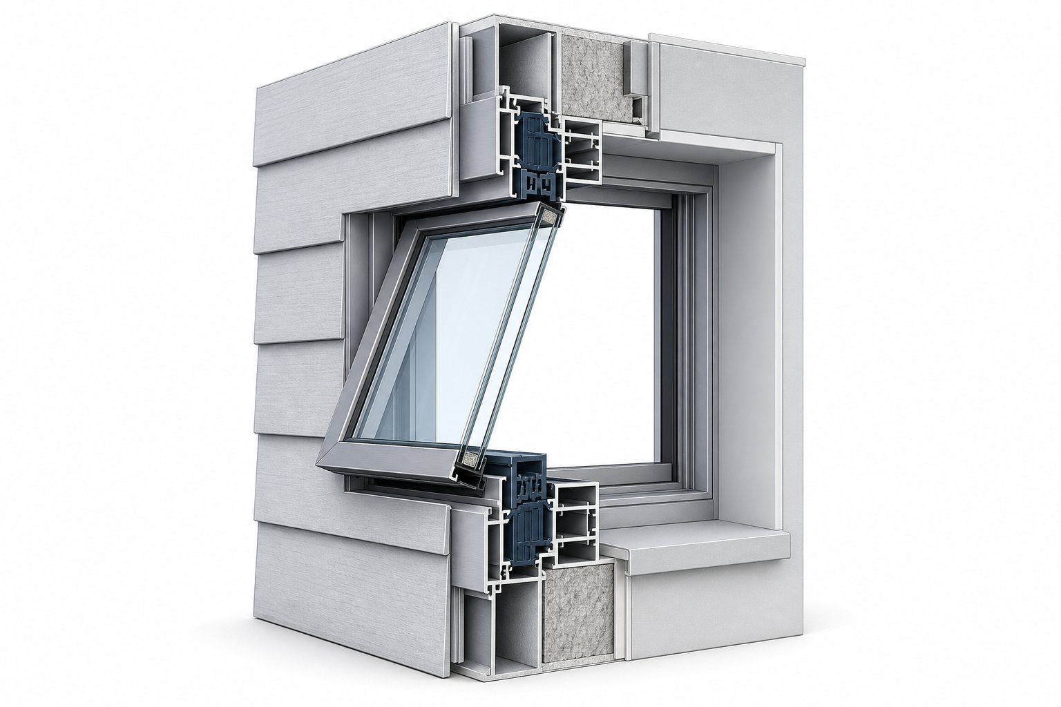
Every aluminium awning window detail set contains three fundamental cross-section views. Think of them as slicing through the window at three different points: once across the top, once across the bottom, and once down the side. Each slice exposes a different set of components and tells a different story about how the frame manages structural loads, water, and air. Together, they form a complete awning window parts diagram that builders and designers can follow from rough opening to finished trim.
Because the awning type window hinges at the top and swings outward from the bottom, the relationship between sash and frame differs at each location. The head carries hinge hardware and must transfer the sash weight into the lintel structure. The sill handles drainage and sealing against wind-driven rain. The jambs manage lateral air sealing and accommodate the friction stay arms that control opening angle. Understanding these three views is essential for anyone specifying or installing awning style windows in Australian residential or commercial projects.
Head Detail and How the Frame Meets the Lintel
The head section cuts horizontally through the top of the frame. In a top hinge awning window, this is where the pivot hardware attaches, so the detail reveals the hinge pocket machined into the frame extrusion, the reinforced section of the sash profile that carries the pivot pin, and the weatherstripping groove that seals the gap when the sash closes. Above the frame, you will see the head flashing dressed over the lintel, lapping down onto the frame's exterior face. A cavity closer or compressible foam strip typically fills the gap between the frame and the structural opening, preventing thermal bridging at this junction.
Sill Detail and the Critical Drainage Path
The sill cross-section is arguably the most important view in any horizontal awning window detail. Water follows gravity, and the sill is where it accumulates. This view shows the sill extrusion's internal drainage channels, small weep slots machined into the exterior face, and the slope built into the profile to direct moisture outward. You will also see the glazing pocket where the insulated glass unit sits within the sash, held in place by snap-in glazing beads and compression gaskets. The sill pan flashing beneath the frame provides a secondary line of defence, catching any water that bypasses the primary seal and directing it back to the exterior.
Jamb Detail and Lateral Weathersealing
The jamb section slices vertically through the side of the frame. It reveals the friction stay track, the weatherstripping compression zone, and how the frame connects laterally to the wall structure via fixing brackets or installation fins. For windows awning style, the jamb detail also shows the clearance required for the sash to swing outward without binding against the reveal. Sealant joints and backing rod positions are clearly dimensioned here, giving installers precise guidance on achieving an airtight perimeter.
| View Type | Key Components Visible | Primary Function |
|---|---|---|
| Head (top) | Hinge pocket, sash pivot profile, weatherstrip groove, head flashing, cavity closer | Transfers sash weight to structure; seals top edge against air and water infiltration |
| Sill (bottom) | Drainage channels, weep slots, glazing pocket, sill pan flashing, compression gaskets | Manages water evacuation; secures glazing unit within sash |
| Jamb (sides) | Friction stay track, lateral fixing brackets, sealant joints, backing rod, weatherstrip | Controls opening mechanism; provides lateral air sealing and structural connection to wall |
Reading these three views together gives you a full picture of how the aluminium frame, sash, glazing, hardware, and weatherproofing layers interact within the wall assembly. The next layer of complexity sits within the frame extrusion itself, where alloy grade, wall thickness, and thermal break technology determine whether the window performs as a high-efficiency building element or a weak point in the envelope.
Frame Alloy Specifications and Thermal Break Technology
Look closely at any aluminium awning window detail and you will find a small notation near the frame extrusion profile, something like "6063-T5" or "6063-T6." These alphanumeric codes carry a lot of weight. They tell the architect and builder exactly what the frame is made of, how strong it is, and how it will behave over decades of exposure to Australian sun, salt air, and seasonal temperature swings.
Understanding Alloy Grades and Extrusion Wall Thickness
The 6063 aluminium alloy dominates window manufacturing globally, and for good reason. It belongs to the 6xxx series, where magnesium and silicon combine to form magnesium silicide precipitates that strengthen the metal during heat treatment. The "T5" temper designation means the extrusion has been cooled from the press and artificially aged at 175-205 degrees Celsius for several hours, producing a tensile strength of 160-200 MPa with excellent corrosion resistance. T6 temper pushes strength higher (190-240 MPa) through a full solution heat treatment and quench cycle, though T5 remains the standard for most residential aluminium awning windows because it balances strength, extrudability, and cost.
What makes 6063 ideal for window frames is its ability to be extruded into complex hollow profiles with wall thicknesses as thin as 1.0 mm while maintaining structural integrity. Australian Standard AS 2047 sets minimum performance requirements that effectively demand frame wall thicknesses of 1.2 mm to 1.6 mm for residential awning windows, depending on span and wind load rating. In detail drawings, wall thickness appears as a dimensioned measurement on the extrusion cross-section. Thinner walls reduce weight and material cost but compromise rigidity under wind pressure. Thicker walls improve deflection resistance, which matters for larger openings in exposed coastal or elevated locations.
How Thermal Break Profiles Function in the Frame
Aluminium conducts heat roughly 1,000 times more efficiently than the polyamide strips used to interrupt that conductivity. Without a thermal break, the interior face of an aluminium frame essentially mirrors the exterior temperature, creating condensation in winter and radiant heat gain in summer. A thermally broken profile splits the extrusion into two separate aluminium sections, an exterior face and an interior face, connected only by a continuous strip of glass-fibre-reinforced polyamide (nylon PA6.6) or polyurethane.
In an aluminium awning window detail drawing, the thermal break appears as a distinct band between the two aluminium profiles, typically ranging from 14.8 mm to 35 mm in width depending on the performance tier. Standard residential systems use breaks around 20-24 mm wide. Premium systems push beyond 30 mm and may incorporate multiple chambers or foam inserts within the polyamide strip for even greater thermal resistance.
The performance difference is dramatic. A non-thermally broken aluminium frame delivers a frame U-value around 5.8-7.0 W/m2K. Basic thermal break systems bring that down to 2.5-3.5 W/m2K, while premium multi-chamber designs achieve 0.8-1.5 W/m2K. For projects targeting high NatHERS star ratings or compliance with stringent NCC energy provisions, the thermal break width shown in the detail drawing is often the single most important specification to verify.
Crimping technology bonds the polyamide mechanically to both aluminium faces, maintaining structural continuity while allowing for different thermal expansion rates between the materials. This connection method appears in detail drawings as a knurled or serrated interface between the strip and the aluminium, a small visual cue that confirms the frame uses genuine mechanical interlock rather than adhesive bonding alone.
Surface Finishes Shown in Detail Specifications
Detail drawings typically include a finish notation alongside the alloy grade. The chosen surface treatment affects durability, colour retention, and aesthetic options. A black awning window, for instance, might specify powder coating to RAL 9005 or an anodised dark bronze, each with different longevity characteristics. Similarly, a white awning window could reference RAL 9016 powder coat or a natural mill-finish anodise, depending on the project's exposure conditions and design intent.
Common surface treatments specified for aluminium awning windows in Australia include:
- Powder coating - Electrostatically applied thermoset polymer cured at high temperature. Film thickness of 60-80 micrometres. Offers the widest colour range, including popular black awning windows finishes and custom colours. Meets durability requirements under AS 3715 for architectural applications. Excellent UV resistance when specified to appropriate performance tiers.
- Anodising - Electrolytic process that grows a hard aluminium oxide layer (typically 15-25 micrometres for architectural use). Provides superior abrasion resistance (300-400 Vickers hardness) and a natural metallic appearance. Ideal for coastal properties where salt spray exposure demands robust corrosion protection. Limited to metallic tones: silver, bronze, champagne, and black.
- PVDF (fluorocarbon) coating - A premium liquid-applied finish containing at least 70% polyvinylidene fluoride resin. Exceptional resistance to UV degradation, chalking, and chemical attack. Service life exceeding 15 years in harsh environments. Higher cost than powder coating but preferred for high-end commercial facades and aluminium clad awning window systems where long-term colour stability is non-negotiable.
Each finish type interacts differently with the thermal break and weathersealing components shown in the detail. Powder coat thickness, for example, must be accounted for in gasket compression calculations, while anodised surfaces require isolation from dissimilar metals at fixing points. These interactions are precisely why the finish specification appears on the detail drawing rather than being treated as a separate cosmetic decision.
With the frame material, thermal performance, and surface protection established, the next critical layer in the detail drawing addresses how all of these components work together to keep water out, a challenge that demands its own layered defence strategy from head to sill.
Weatherproofing Integration and Drainage System Details
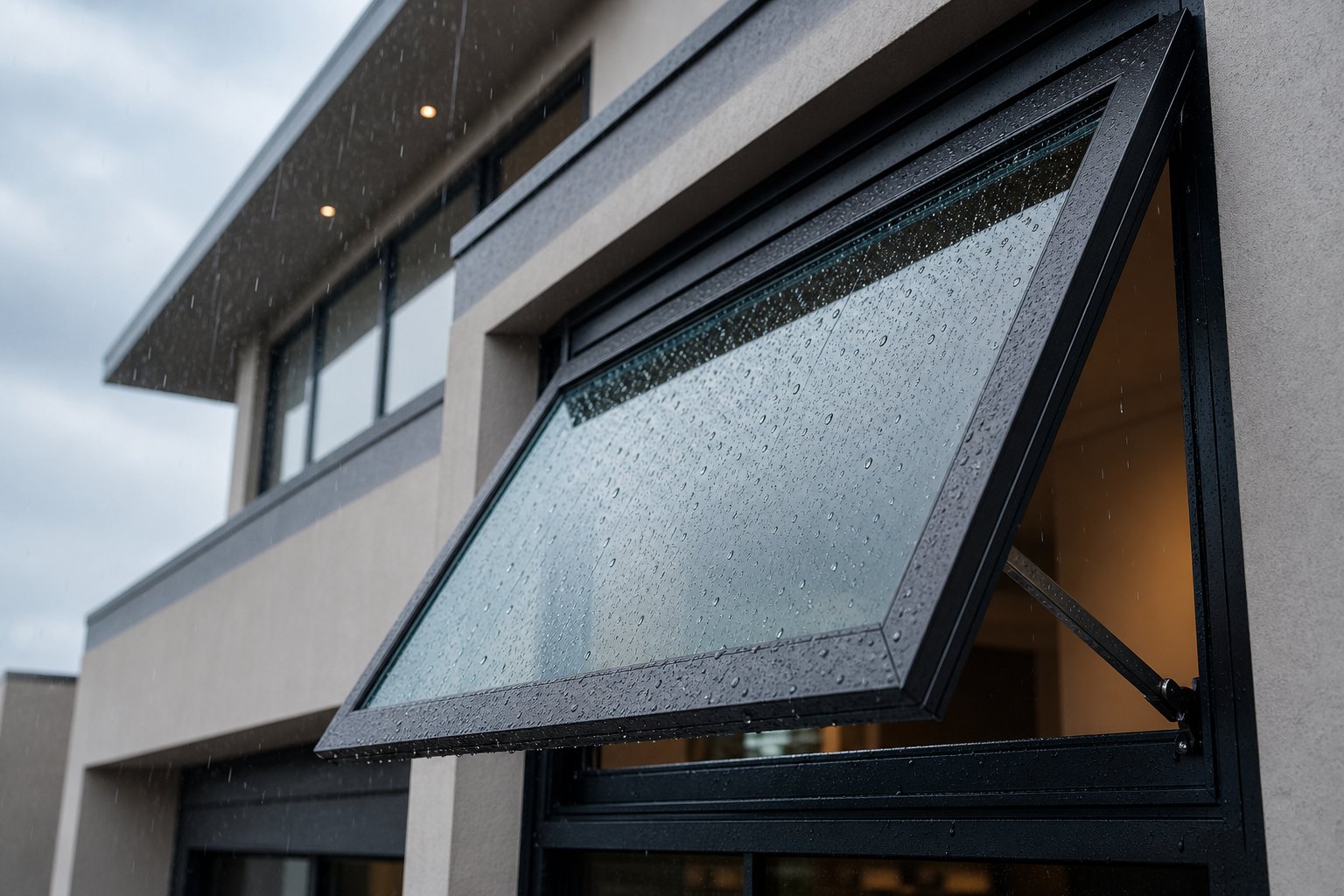
Water does not need much of an invitation. A 1 mm gap under wind pressure, a reversed flashing lap, a blocked weep slot — any one of these can turn an otherwise well-built wall into a moisture trap. For exterior awning windows, the top-hinged outward swing creates a natural advantage: the sash itself acts as a rain deflector when partially open. But that advantage only holds if the frame-to-wall junction manages the water that inevitably reaches it. This is where the aluminium awning window detail earns its keep, mapping out a layered defence system that no single seal or sealant bead could achieve alone.
Flashing Integration at Head, Sill, and Jamb
Flashing around an aluminium awning window follows a strict sequencing logic. Each layer must overlap the one below it so gravity always works in your favour, directing water outward rather than trapping it behind the frame. The installation sequence starts at the lowest point and works upward:
- Sill pan flashing installed first — a pre-formed or field-fabricated membrane that lines the bottom of the rough opening with a slight outward slope. Back-dam heights of 25-50 mm at the interior edge prevent pooled water from migrating inward. The pan catches anything that bypasses the frame's primary seals and routes it to the exterior face of the wall.
- Jamb flashing applied over the sill pan edges — flexible membrane strips dressed up both sides of the opening, overlapping the sill pan at the bottom corners. This overlap ensures water travelling down the jambs drains onto the pan rather than behind it. Sealant beads at the frame-to-jamb junction provide additional air sealing but never serve as the primary water barrier.
- Head flashing installed last — lapped over the top of the jamb membranes and dressed outward onto the weather-resistive barrier. This top layer sheds water away from the lintel zone before it can reach the frame. In brick veneer construction, a metal head flashing (often galvanised steel or aluminium) projects beyond the outer leaf to kick water clear of the window below.
- Weather-resistive barrier lapped over head flashing — the building wrap or membrane above the window overlaps the head flashing by a minimum of 100 mm, completing the shingle-style layering from top to bottom.
Reversing any step in this sequence creates a moisture pocket. Even well-applied sealant cannot compensate for flashing that directs water inward rather than outward. For home awning windows in high-rainfall coastal zones — think northern Queensland or the NSW South Coast — redundant flashing layers and wider back-dams provide additional insurance against wind-driven rain events.
How the Weep Drainage System Prevents Water Damage
No seal is perfectly watertight under sustained wind pressure. The aluminium frame's internal drainage system accounts for this reality by treating water ingress as inevitable and managing it rather than relying solely on exclusion. A pressure-equalised drainage system works through four coordinated stages:
First, the outer weather seal — typically a compression bulb or fin seal — deflects the bulk of wind-driven rain and reduces the volume reaching the interior cavity. Second, a pressure-equalisation chamber behind that outer seal neutralises the air pressure differential that would otherwise force water inward. Small vents connect this chamber to the exterior, allowing pressures to balance so water simply sits rather than being driven through micro-gaps. Third, any collected water drains by gravity along a sloped internal gutter machined into the sill extrusion, flowing toward concealed weep slots positioned at the lowest point. These slots — typically 5 mm x 10 mm rectangular openings or 6 mm diameter holes — discharge water to the exterior face of the frame where it evaporates harmlessly.
The critical insight here is that a weep hole alone does not constitute a drainage system. Without pressure equalisation, wind pressure can hold water inside the cavity or even push it backward past the inner seal. Detail drawings for quality aluminium awning windows show both the weep slot locations and the PE vent positions, confirming the system manages pressure and gravity together. An awning window for bathroom installations, where internal humidity adds condensation load to the frame, relies heavily on this drainage logic to prevent moisture accumulating in the sill cavity.
Weatherstrip Types and Compression Sealing
Weatherstripping appears in the detail drawing as a small profiled shape seated in a machined groove along the frame or sash perimeter. Its job is straightforward: compress when the sash closes to create a continuous air and water seal around the entire opening. Three common types appear in Australian aluminium awning window specifications:
- EPDM compression bulb — a hollow rubber profile that deforms under closing pressure and recovers its shape when the sash opens. Durable across a wide temperature range (-40 to 120 degrees Celsius) and resistant to UV degradation. The most common choice for residential awning windows with screens, where the seal must perform reliably over thousands of open-close cycles.
- Fin seal (brush pile) — flexible polypropylene fibres bonded to a carrier strip. Primarily used in sliding interfaces but occasionally specified at secondary seal positions in awning sashes. Lower compression resistance than EPDM but excellent at accommodating slight frame distortion.
- Multi-chamber hollow gasket — a more complex EPDM profile with two or three internal chambers that collapse progressively. Provides superior acoustic sealing and higher air pressure resistance. Specified for awning kitchen windows and other openings in noise-affected locations or high-wind zones where air infiltration rates must meet stringent NCC requirements.
Compression distance — the amount the weatherstrip deforms when the sash latches — is dimensioned on the detail drawing, typically 2-3 mm for residential systems. Too little compression and the seal leaks air. Too much and the hardware strains to close, accelerating wear on both the gasket and the locking mechanism. This balance between seal performance and operational ease is precisely what the detail drawing communicates to the installer.
Weatherproofing keeps water out. But the glazing assembly sealed within that protected frame determines how much heat passes through — a relationship where glass thickness, gas fill, and coating position each shift the energy equation in measurable ways.
Glazing Assembly and Energy Performance Metrics
The frame keeps water out and the thermal break limits conductive heat flow through the aluminium itself. But the largest surface area in any window is glass, and glass is where most thermal energy actually transfers. In an aluminium awning window detail, the glazing assembly occupies the central portion of the sash cross-section, and the specifications annotated there — pane thickness, spacer type, cavity width, gas fill, and Low-E coating surface position — collectively determine whether the window helps or hinders your building envelope's energy performance.
Glass Thickness, Spacer Type, and Gas Fill in the Detail
A typical detail drawing for modern awning windows shows the insulated glass unit (IGU) as two or three parallel lines representing individual panes, separated by a rectangular spacer bar at the perimeter. Each element carries a specification notation.
Glass thickness for residential aluminium awning windows in Australia commonly ranges from 4 mm to 6 mm per pane, with 5 mm being a standard default for double-glazed units. A large awning window spanning 1,200 mm or more may require 6 mm glass to meet deflection limits under wind load, particularly in higher wind classifications per AS 2047. Triple-glazed configurations add a third pane or a suspended polymer film between the outer layers, pushing total IGU thickness from the standard 20-24 mm range up to 36-44 mm — a dimension that directly affects sash depth and glazing pocket design.
The spacer bar separating panes appears in the detail as a small rectangular profile at the glass edge. Traditional aluminium spacers conduct heat efficiently, creating a cold bridge at the perimeter that raises condensation risk. Warm-edge spacers — made from stainless steel, thermoplastic, or foam-based composites — reduce this edge conductivity and improve whole-unit U-values by 0.1-0.2 W/m²K compared to standard aluminium spacers. Detail drawings for higher-performance systems specify warm-edge spacers explicitly.
Between the panes sits the gas fill cavity. Air-filled cavities provide baseline insulation, but argon gas (roughly 34% less conductive than air) is the standard upgrade for double awning window configurations. Cavity widths of 12-16 mm optimise argon's insulating benefit. Krypton gas performs better still in narrower cavities (8-12 mm), making it useful where sash depth is constrained, though its higher cost limits it to premium applications. For a big awning window in an exposed position, argon-filled double glazing strikes the practical balance between performance and budget.
Connecting Detail Design to U-Value and SHGC Ratings
These glazing choices translate directly into two metrics that matter for NCC compliance and NatHERS modelling: U-value and Solar Heat Gain Coefficient (SHGC).
U-value measures the rate of non-solar heat transfer through the complete window assembly — frame, spacer, and glass combined. Lower numbers mean better insulation. SHGC is a ratio from 0 to 1 indicating how much solar radiation passes through as indoor heat. A low SHGC blocks solar gain (ideal for west-facing large awning windows in cooling-dominated climates), while a higher SHGC admits passive warmth (useful for south-facing glass in heating-dominated zones like Hobart or the ACT). In practical terms, getting SHGC wrong on a west-facing opening means your air conditioner works overtime every summer afternoon.
The position of the Low-E coating within the IGU shifts both metrics. Placing it on surface 2 (inner face of the outer pane) maximises solar rejection — suited to Queensland and northern NSW. Placing it on surface 3 (outer face of the inner pane) retains more passive solar heat — better for Victoria, Tasmania, and highland regions. Double-silver or triple-silver sputtered Low-E coatings achieve lower SHGC values than single-silver pyrolytic versions, giving specifiers finer control over solar performance in long awning windows running along north or west facades.
| Glazing Configuration | Typical Whole-Window U-Value (W/m²K) | Typical SHGC Range | Best Suited Climate |
|---|---|---|---|
| Single glazed, no coating | 5.5 – 6.2 | 0.70 – 0.80 | Mild zones with minimal heating/cooling demand |
| Double glazed, air fill, no Low-E | 2.7 – 3.3 | 0.55 – 0.70 | Moderate climates; basic compliance |
| Double glazed, argon fill, Low-E (surface 2) | 1.8 – 2.4 | 0.25 – 0.40 | Cooling-dominated; west/north-facing openings |
| Double glazed, argon fill, Low-E (surface 3) | 1.8 – 2.4 | 0.40 – 0.55 | Heating-dominated; passive solar design |
| Triple glazed, argon/krypton, dual Low-E | 0.8 – 1.4 | 0.20 – 0.45 | Extreme cold zones; high-performance envelopes |
Air infiltration rate — the third performance metric — depends less on the glazing itself and more on how the IGU is secured within the sash. The glazing bead and gasket system shown in the detail drawing handles this. Snap-in aluminium or co-extruded PVC beads clamp the glass against continuous EPDM gaskets on both the interior and exterior faces. These gaskets compress evenly around the IGU perimeter, creating an airtight seal that prevents convective heat loss around the glass edge. For a fixed awning window (a non-operable panel paired alongside an operable sash), the glazing bead system is the only seal required since there is no sash-to-frame interface to manage.
Modern awning window systems designed for Australian conditions typically target whole-window U-values between 1.8 and 2.8 W/m²K with argon-filled double glazing and Low-E coatings — a range that satisfies most NCC Section J and NatHERS requirements without the cost premium of triple glazing. The detail drawing captures all of these choices in a single cross-section, giving the builder and certifier a clear record of what performance the installed window will deliver.
Performance specifications only matter if the window is installed correctly within the wall assembly. The method of installation — whether a nail-on fin for new builds or a retrofit frame slipped into an existing opening — introduces its own set of dimensional tolerances and flashing sequences that the detail drawing must communicate with equal precision.
Installation Details for New Construction and Retrofit
A perfectly specified frame means nothing if it lands in a poorly prepared opening or gets flashed in the wrong sequence. The aluminium awning window detail drawing does more than describe the window itself — it maps how the frame connects to the surrounding wall structure, where shims sit, what clearances are required, and how flashing integrates with the water-resistive barrier. Two fundamentally different installation approaches exist, and choosing the wrong one for your wall assembly creates problems that no amount of sealant can fix after the fact.
The distinction comes down to timing. Are you building a new wall from scratch, with the sheathing and weather barrier still accessible? Or are you sliding a replacement awning window into an existing opening where the cladding stays in place? Each scenario demands its own frame type, fixing method, and flashing strategy — all of which the detail drawing communicates through specific dimensional notations and material callouts.
Nail-On Fin Details for New Wall Assemblies
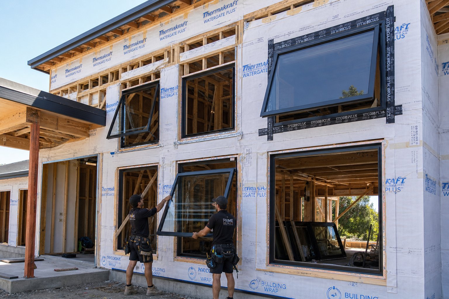
In new construction, aluminium awning windows typically arrive with a perimeter installation fin — a thin flange extending outward from the frame that sits flat against the wall sheathing. This fin serves two purposes: it holds the window in position during installation, and it provides a surface for the weather-resistive barrier and flashing tape to lap over, creating a continuous drainage plane around the frame perimeter.
For aluminium frames, these fins are non-integral — meaning they are mechanically attached to the frame extrusion during manufacturing rather than formed as a single piece. This gives the installer some adjustment flexibility. The fin can accommodate slight irregularities in the sheathing plane without transferring stress into the frame itself, which protects weatherstrip alignment and hardware operation over time.
The detail drawing for a nail-on fin installation shows the fin sitting flush against the structural sheathing (typically plywood or oriented strand board), with self-adhered flashing membrane lapping over the fin edges in a specific sequence. Fasteners — preferably screws rather than nails for better holding strength and adjustability — pass through pre-punched holes in the fin at intervals specified by the manufacturer, typically 150-200 mm apart.
A critical point the detail communicates: the bottom fin is not sealed. Leaving the bottom edge unsealed creates a drainage path for any moisture that reaches the sill pan, allowing it to weep outward rather than pooling behind the frame. This deliberate gap is often misunderstood on site, where installers instinctively want to seal every edge.
The installation sequence for a nail-on fin aluminium awning window in a new wall assembly follows this order:
- Prepare the rough opening to the dimensions specified on the detail drawing, ensuring square, level, and plumb conditions
- Install the sill pan flashing with back-dam and end-dams, sloped toward the exterior
- Apply jamb flashing strips over the sill pan edges, extending up both sides of the opening
- Set the window into the opening from the exterior, resting the sill fin on the sheathing
- Check plumb, level, and square using a spirit level; insert shims at designated points before fastening
- Fasten the fin to the sheathing with corrosion-resistant screws at specified intervals, starting at the top corners
- Apply self-adhered flashing tape over the jamb fins, lapping onto the sheathing by at least 50 mm
- Apply head flashing tape over the top fin, overlapping the jamb tape ends
- Lap the weather-resistive barrier over the head flashing, completing the shingle-style drainage sequence
- Leave the bottom fin unsealed to maintain the drainage path
This method works for timber-framed walls with sheet sheathing — the dominant construction type for new residential builds across most of Australia. For steel-framed construction, the same principle applies but fastener type changes to self-drilling screws rated for the stud gauge.
Retrofit Frame Details for Replacement Projects
Replacing an old timber or aluminium window in an existing home presents a different challenge. The exterior cladding — whether brick veneer, rendered masonry, weatherboard, or fibre cement — stays in place. There is no exposed sheathing to attach a fin to, and disturbing the cladding to access the structural frame would blow out both cost and project scope.
A replacement awning window for this scenario uses a retrofit frame (sometimes called a sub-frame or reveal-fix frame) that sits inside the existing opening and fastens directly through its sides into the surrounding structure. The detail drawing shows the frame profile without any perimeter fin, instead featuring pre-drilled fixing lugs or screw slots along the jamb and head sections. These fixings pass through the frame and into the timber reveal, masonry, or steel lintel behind.
Because the retrofit frame occupies space within the existing opening, the visible glass area shrinks slightly compared to the original window. For a small awning window in a bathroom or laundry, this reduction is minimal — perhaps 10-15 mm per side. For larger openings, the dimensional trade-off is more noticeable and should be discussed with the homeowner before ordering. The detail drawing dimensions both the overall frame size and the clear glass area, making this trade-off explicit.
Weatherproofing a retrofit installation relies on sealant rather than membrane flashing, since the weather-resistive barrier behind the cladding cannot be accessed or modified. A continuous bead of exterior-grade polyurethane or silicone sealant bridges the gap between the new frame and the existing reveal or cladding edge. The detail drawing specifies the sealant joint width (typically 6-10 mm) and depth, along with backing rod diameter to control the sealant profile and prevent three-sided adhesion that would restrict joint movement.
The installation sequence for a retrofit frame differs significantly:
- Remove the existing window sash, hardware, and any deteriorated sections of the old frame
- Inspect the remaining reveal structure for rot, corrosion, or damage — repair before proceeding
- Measure the clear opening dimensions and confirm they match the custom awning window ordered for the project
- Apply a sill flashing membrane to the existing sill if accessible, or ensure the existing sill slopes outward
- Position the new frame within the opening, centred and shimmed to achieve plumb and level
- Fasten through the frame into the structural reveal using countersunk screws at 300-400 mm centres
- Install backer rod into the perimeter gap between frame and reveal
- Apply continuous sealant bead to the exterior joint, tooling for a concave profile that sheds water
- Fit interior architrave or trim to conceal the interior gap and any shim points
Retrofit installations are common across older Australian housing stock — fibro cottages, double-brick homes from the 1960s-80s, and weatherboard Queenslanders all present variations on this approach. Each wall type introduces slightly different fixing requirements, which is why the detail drawing must specify the substrate type and corresponding fastener.
Rough Opening Preparation and Shimming Requirements
Both installation methods depend on a correctly sized rough opening. The detail drawing specifies the nominal awning window size — the outer frame dimension — and adds a clearance tolerance on each side. Standard practice calls for 5-10 mm clearance per side between the frame and the rough opening structure. This gap accommodates shimming, allows for minor framing irregularities, and provides space for expanding foam insulation that seals the cavity against air leakage.
Too tight and the frame binds, distorting the extrusion and compromising hardware operation. Too loose and shimming becomes unreliable, sealant joints stretch beyond their movement capacity, and the window may shift under wind load. For awning windows sizes outside standard ranges — particularly tall narrow configurations or wide horizontal units — manufacturers often specify tighter tolerances because the frame's aspect ratio makes it more sensitive to racking forces.
Shim placement is not arbitrary. The detail drawing marks specific shim points that correspond to structural load paths and hardware locations:
- Sill shims — positioned directly below the jamb-to-sill corner junctions and at any intermediate mullion points. These carry the dead weight of the frame and glazing, transferring it into the rough sill framing.
- Jamb shims — placed at hinge locations and locking points to resist operational forces. For awning window standard sizes, this typically means shims at 150 mm from each corner and at 400-600 mm centres between.
- Head shims — used only to prevent the frame from lifting under negative wind pressure, not to carry weight. Placed at the same horizontal positions as the sill shims to maintain parallel alignment.
Shim material matters too. Hardwood or engineered plastic shims are preferred over softwood packers that can compress over time and allow the frame to settle. The detail drawing may specify shim material directly, or reference the manufacturer's installation guide for approved packing options.
An awning window size chart from the manufacturer typically lists both the nominal frame dimension and the required rough opening dimension for each standard unit. Builders working from these charts can frame openings accurately during the rough-in stage, avoiding the costly rework that comes from discovering a 5 mm discrepancy after the cladding is already on. For a custom awning window ordered to non-standard dimensions, the rough opening size is calculated from the frame dimension plus the specified clearance — a straightforward calculation, but one that must account for any sub-sill or packing that sits between the frame and the structural framing.
With the frame correctly sized, shimmed, and fastened within its opening, the final layer of the installation puzzle involves compliance — ensuring the chosen detail meets the performance requirements dictated by climate zone, wind region, and the applicable building code provisions that govern the project.
How Building Codes and Climate Zones Shape Detail Design
Climate dictates which aluminium awning window detail is appropriate for a given project. A residential awning windows installation in Darwin faces cyclonic wind loads and extreme solar gain. The same window type in Hobart contends with heat loss and condensation risk. The detail drawing must respond to these regional pressures, and the regulatory framework ensures it does.
Climate Zone Requirements That Shape Detail Selection
Australia's National Construction Code divides the country into eight climate zones, each imposing different thermal performance thresholds on the building envelope. Windows — the weakest thermal link in most walls — bear the brunt of these requirements. In cooling-dominated zones (1-3, covering tropical and subtropical regions), NCC Section J demands low SHGC values and robust drainage detailing to handle monsoonal rain. In heating-dominated zones (6-8, covering alpine and cold temperate areas), U-value limits tighten, pushing specifications toward wider thermal breaks and triple-glazed IGUs.
Wind region classification adds another layer. AS 2047 assigns structural performance requirements based on terrain category and geographic wind speed. Awning casement windows in Region C or D (cyclone-prone areas of northern Queensland, the NT, and parts of WA) must demonstrate structural adequacy under design wind pressures exceeding 2.5 kPa — a requirement that directly affects frame wall thickness, glazing selection, and hardware specification shown in the detail. Coastal salt-spray zones demand corrosion-resistant finishes and stainless-steel hardware, further shaping what appears on the drawing.
Bushfire Attack Level (BAL) ratings introduce yet another variable. At BAL-29 and above, AS 3959 requires metal-framed windows with specific glazing types and screening. Aluminium awning windows naturally satisfy the frame material requirement, but the detail must confirm compliant glass thickness and mesh specifications for the relevant BAL rating.
How Architects Specify Awning Window Details in Construction Documents
Specification writers organise window requirements using structured classification systems. Internationally, CSI MasterFormat Section 08 51 13 covers aluminium windows, and this numbering convention appears in Australian projects that follow NATSPEC's workgroup structure — the local adaptation most architectural practices use for construction documentation. Under this section, the specifier defines acceptable awning window styles, performance criteria, material standards, finish requirements, and submittal expectations in a format that contractors and suppliers can price and procure against.
When reviewing detail submittals from manufacturers, architects evaluate whether the proposed system satisfies the project's specific conditions. A submittal package for awning windows and doors typically includes full-size cross-section details, structural calculations, thermal modelling results, and test reports. The architect checks these against a defined set of criteria before granting approval to proceed.
Key specification criteria architects evaluate when reviewing aluminium awning window submittals include:
- Structural adequacy — frame deflection under design wind pressure must not exceed span/150 for the specified opening size, verified by engineering calculation or independent test report per AS 2047
- Thermal performance compliance — whole-window U-value and SHGC must meet or exceed the values assumed in the NatHERS energy model or NCC Section J deemed-to-satisfy provisions for the project's climate zone
- Water management — detail must demonstrate a complete drainage path from pressure-equalisation chamber through weep slots to exterior, with flashing integration compatible with the specified wall system
- Air infiltration — tested air leakage rate must comply with the maximum allowable rate for the window's performance classification under AS 2047
- Compatibility with wall assembly — frame depth, fin configuration, and fixing method must suit the specified construction type (timber frame, steel frame, concrete, or masonry) without requiring non-standard modifications
- Finish durability — surface treatment must be appropriate for the project's exposure conditions, with warranty periods and test compliance (AS 3715 for powder coating, AS 1231 for anodising) documented
- Hardware and operation — friction stays, locking mechanisms, and seals must be rated for the specified number of operating cycles and compatible with any accessibility or security requirements
A rejected submittal sends the supplier back to revise — a costly delay that reinforces why builders and developers benefit from selecting awning casement windows systems with comprehensive technical documentation from the outset. The more complete a manufacturer's detail package, the faster it clears the architect's review and the sooner procurement can begin.
This compliance and specification framework sets the stage for the final practical question: how do you move from understanding these details on paper to selecting an actual aluminium awning window system that delivers on them for your specific project?

Selecting an Aluminium Awning Window System for Your Project
Knowing how to read an aluminium awning window detail is one thing. Choosing a system that actually delivers on those details across dozens or hundreds of openings is a different challenge entirely. The gap between a well-drawn cross-section and a well-performing installed window comes down to manufacturer capability — specifically, whether their technical documentation, production consistency, and supply model match the demands of your project.
What to Look for in Manufacturer Technical Documentation
A manufacturer's technical package reveals how seriously they treat performance. Incomplete documentation is a red flag, regardless of how competitive the pricing looks. When evaluating aluminium awning windows for a residential development or commercial fit-out, the submittal package should give you everything an architect needs to approve the system without chasing supplementary information.
Strong documentation includes full cross-section details at head, sill, and jamb — not simplified marketing diagrams, but dimensioned drawings showing thermal break width, drainage paths, weatherstrip positions, and glazing pocket geometry. It also includes tested performance data: U-values, SHGC ratings, air infiltration results, and water resistance classifications per AS 2047. Hardware specifications should name the friction stay brand, cycle rating, and maximum sash weight capacity. For push out awning windows with chain winder or motorised actuator options, the documentation should clarify motor torque ratings and integration details for home automation systems.
Builders sourcing the best awning windows for multi-unit projects need this level of transparency to avoid costly surprises during certification or on-site installation. Vague spec sheets that list only frame depth and colour options are not sufficient for projects where NCC compliance and council approval depend on verified performance data.
Evaluating Aluminium Awning Window Systems for Your Project
Project-based supply operates differently from retail purchasing. When you are fitting out an apartment complex, a row of townhouses, or a commercial kitchen requiring a pass-through awning kitchen window for servery ventilation, you need a supplier who can hold consistent quality across a production run, coordinate staged deliveries to match construction sequencing, and provide technical support when site conditions deviate from the drawings. A pass thru awning window for a hospitality fit-out, for instance, may require non-standard sill heights and hardware configurations that only a project-oriented manufacturer can accommodate efficiently.
When comparing systems, evaluate against these criteria:
- Detail drawing completeness — full head, sill, and jamb sections with dimensions, not simplified outlines
- Thermal break presence and width — confirmed polyamide break with stated width in millimetres
- Drainage system design — pressure-equalised weep system with documented slot positions
- Available sizes and configurations — standard range plus custom capability for non-standard openings
- Finish options and durability — powder coating to AS 3715, anodising options, and colour range
- Hardware and automation — friction stay ratings, locking systems, and motorised awning windows options for high or hard-to-reach openings
- Project supply capability — staged delivery, bulk pricing, technical coordination, and after-sales support
Affordable awning windows exist at every performance tier, but cost should be weighed against the completeness of the system rather than frame price alone. A cheaper unit that lacks proper drainage detailing or ships without tested performance data will cost more in rework, failed inspections, and warranty claims than a slightly higher-priced system with full documentation and proven site performance.
For readers looking to see how these technical principles translate into a real product offering, MEICHEN's MA100 Awning Window system provides a practical example of a project-supply aluminium awning window designed for Australian residential and commercial applications. It is worth exploring as a reference point when comparing how different manufacturers present their technical details, frame configurations, and supply models for builders and developers working at scale.
Frequently Asked Questions About Aluminium Awning Window Details
1. What are the three main cross-section views in an aluminium awning window detail?
The three primary views are head (top), sill (bottom), and jamb (sides). The head detail shows how the hinge pocket and frame connect to the lintel structure. The sill detail reveals drainage channels, weep slots, and the glazing pocket — it is the most critical view for water management. The jamb detail exposes the friction stay track, lateral fixing brackets, and weatherstrip compression zones. Together, these three sections provide builders and architects with a complete picture of how the window integrates structurally, thermally, and weatherproofing-wise within the wall assembly.
2. What does a thermal break do in an aluminium awning window frame?
A thermal break is a continuous strip of glass-fibre-reinforced polyamide (PA6.6) or polyurethane that separates the interior and exterior aluminium faces of the frame. Because aluminium conducts heat roughly 1,000 times more efficiently than polyamide, this strip dramatically reduces heat transfer through the frame. Non-thermally broken frames have U-values around 5.8-7.0 W/m²K, while thermally broken systems achieve 2.5-3.5 W/m²K for standard residential profiles and as low as 0.8-1.5 W/m²K for premium multi-chamber designs. The thermal break width — typically 20-35 mm — is one of the most important specifications to verify on the detail drawing for NCC energy compliance.
3. How does the weep drainage system work in aluminium awning windows?
The weep system operates on the principle that no seal is perfectly watertight under sustained wind pressure, so it manages water ingress rather than relying solely on exclusion. It works through four stages: an outer weather seal deflects bulk rain, a pressure-equalisation chamber neutralises air pressure differentials that would force water inward, collected water drains by gravity along a sloped internal gutter in the sill extrusion, and finally exits through small weep slots (typically 5 mm x 10 mm) on the exterior face. Without pressure equalisation, wind can hold water inside the cavity or push it backward — which is why quality detail drawings show both weep slot and PE vent positions.
4. What is the difference between nail-on fin and retrofit frame installation for aluminium awning windows?
Nail-on fin installation suits new construction where wall sheathing and the weather-resistive barrier are still accessible. The frame arrives with a perimeter flange that sits flat against the sheathing, and membrane flashing laps over it in a specific sequence to maintain the drainage plane. Retrofit frame installation is designed for replacement projects where existing cladding stays in place. The frame sits inside the existing opening and fastens directly through its sides into the surrounding structure, relying on sealant joints rather than membrane flashing for weatherproofing. Choosing the wrong method for your wall assembly creates water management problems that cannot be fixed with sealant alone.
5. What specifications do architects check when reviewing aluminium awning window submittals?
Architects evaluate submittals against several key criteria: structural adequacy (frame deflection under design wind pressure not exceeding span/150 per AS 2047), thermal performance compliance (whole-window U-value and SHGC meeting NatHERS or NCC Section J requirements), water management (complete drainage path with pressure-equalised weep system), air infiltration rates, compatibility with the specified wall assembly, finish durability appropriate for the project's exposure conditions, and hardware cycle ratings. Submittals are organised under CSI MasterFormat Section 08 51 13 (or the NATSPEC equivalent) and must include dimensioned cross-section details, test reports, and thermal modelling results.